I haven't decided on caps for my mono's yet. Still researching the most economical/practical solution there.
I ended up buying these, made better use of space in my case: https://www.mouser.hk/ProductDetail/598-382LX333M080B092/
Decided to go with a single rail SLB CapMx for each mono block that will be fed off of Antek 300Va 50V transformers. Question on the transformers. Is everyone using Antek transformers for monoblocks wiring the secondaries in parallel? Do the primaries need to be wired in paralleled also? And phasing of primaries figured out?
Yes, primaries are wired in parallel as in the typical FW supply. 50VAC secondaries in parallel also. See Antek spec sheet:
https://www.antekinc.com/content/AS-3450.pdf
Primaries red with red, black with black. Secondaries green with green, blue with blue.
https://www.antekinc.com/content/AS-3450.pdf
Primaries red with red, black with black. Secondaries green with green, blue with blue.
ZM - looking for advice.
I started measuring in REW at 1W, 5W, and 10W. I printed a sheet to write down distortions while ramping up from 30V-37V.
At first I thought my distortion figures were way out of whack compared to what you and BenMah were showing, but I think what I'm seeing is I need to turn up the voltages.
I noticed the trend that 2nd order distortion kept dropping as SIT drain voltage increased. And 3rd order moves up.
I got to 46V and wanted to check here before I try too high and let magic smoke out of something...
Now I'm wondering.
How high CAN the drain voltage go?
How high SHOULD it go?
Background facts: 2SK182ES, 2A3, 67.4V Rail Voltage
Both channels track in a similar fashion.
Take a look at this:
SIT measurements, Mu Follower, and amplifier build
60V supply and 3A, so Vds about 30V?
Lower distortion with higher current, no idea of distribution of harmonics. Probably worth investigating.


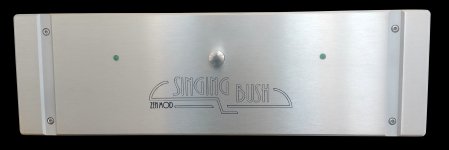
banderson546 - That's a gorgeous front panel! 
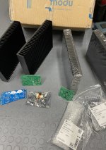
I finally got all my parts to (crossing fingers) get back to work on the Singing Bush. I haven't forgotten.
A little teaser of the filter boards for the PSU. Thanks again to Botte for the PCB design!!!
![63615323404__C2E2927B-0E85-430E-8CAD-C1CD62FDCF5A[5399].jpg](https://www.diyaudio.com/community/data/attachments/832/832766-a5cec4d7534e7cdc7545ecec4799ab71.jpg?hash=pc7E11NOfN "63615323404__C2E2927B-0E85-430E-8CAD-C1CD62FDCF5A[5399].jpg")
I finally got all my parts to (crossing fingers) get back to work on the Singing Bush. I haven't forgotten.
A little teaser of the filter boards for the PSU. Thanks again to Botte for the PCB design!!!
Guess I should have asked this earlier, but is it necessary for the IXFN and THF to be on the same heat sink for each channel?
I mounted them one on each radiator in a mono amplifier with 2 radiators 400x160x83 mm, it works perfectly
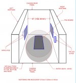
So, anyone have any thoughts on the chassis layout in post #155? Thanks!
The Singing Bush
Are you thinking like the layout in post 520 in other thread?
Suggestion: Mount transformer vertically at the front of the chassis. A Simpson Strong Tie A24 bracket works great as a transformer mount:
https://www.homedepot.com/p/Simpson-Strong-Tie-2-in-x-3-7-8-in-x-2-1-2-in-Galvanized-Angle-A24/100375162
https://www.homedepot.com/p/Simpson-Strong-Tie-2-in-x-3-7-8-in-x-2-1-2-in-Galvanized-Angle-A24/100375162
Yes, rhthatcher! Thank you for tracking that one down. I thought there had been a similar layout but I couldn’t find it. So it appears thermal tracking between devices is not an issue if they are on opposite sides of the chassis?
Thank you Ben! Yes, I know the diagram is a little crude. The shaded element in front is a vertically mounted transformer. A few weeks ago I found some .125” thick 2” x 4” aluminum angle on flea bay that was precut into 1-3/4” wide pieces. I used one in the BabelJ2 I just finished and it worked great to hold that transformer vertically to the baseplate of the chassis.
2" X 4" ALUMINUM ANGLE 1/8" THICK 1 3/4" IN LENGTH (8 PIECES) | eBay
Last edited:
- Home
- Amplifiers
- Pass Labs
- The Singing Bush Tips 'n' Tricks