I know it's literally impossible for me to finish a project. But some stuff that was published over on Erinsaudiocorner got me wondering if I should try a conventional two-way.
In a nutshell, for two or three years I've been aware that you can use the dimensions of the loudspeaker cabinet to get directivity control down to a lower frequency than you might expect. Basically you can extend directivity control down to about 500-700Hz by manipulating the baffle dimensions.
The thing that really caught my attention, in his recent measurements, was how similar the JBL 708P performs, when compared to the JBL M2.
I have quite a few two-way speakers, including the very well reviewed Infinity IL50s. And the IL50s always left me cold, they're nowhere near as dynamic as my Waslo Cosynes or my Yamaha DXR12s.
But the 708P review got me wondering that maybe the combination of a 7" or 8" woofer with a horn loaded compression driver (like the 708P) might be the ticket.
So let's look at some data...
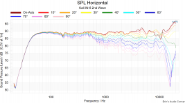
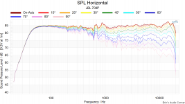
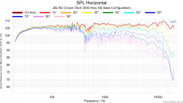
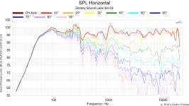
Second, here's the "horizontal polar response" for the Kali IN-8, JBL 708p, JBL M2 and Danley SH-50, in that order.
Data courtesy of Erin's Audio Corner.
In a nutshell, for two or three years I've been aware that you can use the dimensions of the loudspeaker cabinet to get directivity control down to a lower frequency than you might expect. Basically you can extend directivity control down to about 500-700Hz by manipulating the baffle dimensions.
The thing that really caught my attention, in his recent measurements, was how similar the JBL 708P performs, when compared to the JBL M2.
I have quite a few two-way speakers, including the very well reviewed Infinity IL50s. And the IL50s always left me cold, they're nowhere near as dynamic as my Waslo Cosynes or my Yamaha DXR12s.
But the 708P review got me wondering that maybe the combination of a 7" or 8" woofer with a horn loaded compression driver (like the 708P) might be the ticket.
So let's look at some data...
Second, here's the "horizontal polar response" for the Kali IN-8, JBL 708p, JBL M2 and Danley SH-50, in that order.
Data courtesy of Erin's Audio Corner.
Attachments
how does the phase look on the 708p ?
I'm a time alignment guy and have been closely following anything on the Yamaha fir filter stuff...………………
I think closer phase integration can help on dynamics, or snap, a little easier for intelligibility.
Of course, some other things add to dynamics/snap, like "a sharp leading edge" (djk, r.i.p.) such as a compression driver on a good horn, low distortion helps too.
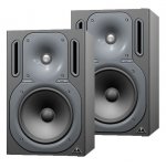
That horn kali looks good, but i like a hf horn to be more like the Berenger truth b2031's horn better (first pic), very "soap dish" as you say, working towards no reflections.
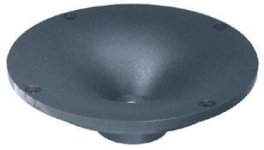
or the lowly pyle round mcm horn (2nd pic) from long ago (take 1 3/8" screw on).
I just can't wrap my mind around the jbl's throat peak to spread reflections.
Why not have no reflections ?
I'm a time alignment guy and have been closely following anything on the Yamaha fir filter stuff...………………
I think closer phase integration can help on dynamics, or snap, a little easier for intelligibility.
Of course, some other things add to dynamics/snap, like "a sharp leading edge" (djk, r.i.p.) such as a compression driver on a good horn, low distortion helps too.
That horn kali looks good, but i like a hf horn to be more like the Berenger truth b2031's horn better (first pic), very "soap dish" as you say, working towards no reflections.
or the lowly pyle round mcm horn (2nd pic) from long ago (take 1 3/8" screw on).
I just can't wrap my mind around the jbl's throat peak to spread reflections.
Why not have no reflections ?
Attachments
Last edited:
I haven’t been on this forum for a while but your post is interesting as always. I will break down your problem in the following order.
1. Your whole house is connected acoustically. The total volume is so large that you will have a very low Schroeder frequency and develop a sustained diffused field, i.e. constant volume across distance. Assuming you’re not going to change your house layout, the only thing you could do is to add absorption as you already noted, and/or putting diffusers (such as WhisperWave quoted in #34). Decorative heavy drapes hanging across the whole ceiling is another option. Others already mentioned to make the room acoustically smaller by using divider. I personally think a row of plants between kitchen and living room is a pretty wife-friendly option.
2. Radiation pattern is useful at sufficient high frequency and when number of reflection is low, but mode is also very useful when frequency is low. Anyhow, they are respective mathematical asymptotic to an exact formulation. There is also a simple source-to-pattern mapping. A pressure source is monopole, and a velocity source is dipole. Cardioid is just a pressure source colocates with a velocity source.
Using this concept, LX mini can be understood as monopole at low frequency, cardioid at crossover (monopole + dipole), gradually transition into a cardioid by attenuating the back wave from the diagram (while xo attenuates the monopole part), and eventually beaming forward (and almost nothing backward) because the shape of the cone and the material of cone to even out the cone modes. No baffle/ waveguide/ horn is needed here to control the pattern. You can change the 1:1 ratio to something else making a super cardioid if you like, which trades directivity with back lobe strength.
Pressure source excites the mode maximally when placed at pressure anti-node, i.e. walls, and velocity source excites the room modes maximally when placed at a velocity anti-node, which moves around in the room depends on order of mode and wavelength of the mode. In short, the cardioid subwoofer is just a way to excite the modes more equally regardless of its placement.
Your ceiling is pretty tall so you also need to worry about vertical modes. You could hang a few subwoofers from the ceiling to manage the vertical modes following the four speakers around corners idea for mode management.
3. For your low frequency problem, there is a potential brute force solution by placing lots of subwoofers across "the whole house", and do an optimization to confine the low frequency sound field mostly in the living room. You would need to run your own optimization program with either an accurate acoustic model of the house, or tons of manual measurement. It seems there are a few free FDTD acoustic solver available, such as this one, but I have no personal experience using it.
The thing that really caught my attention, in his recent measurements, was how similar the JBL 708P performs, when compared to the JBL M2.
I'm continually surprised you haven't picked up a pair of JBL 708 (or 705) yet.
I'm continually surprised you haven't picked up a pair of JBL 708 (or 705) yet.
Oh I know. At some point I really need to accept that:
1) I'm terrible at finishing projects
2) I have a really hard time making things look nice
For instance, I invested about 40 hours in the latest iteration of this project, over the last week. As we speak, I have some contractors doing work on our kitchen. I'm paying the contractors about $160 an hour for two people, which works out to $80 per hour per person.
If I'd spent 40 hours just working on my own kitchen, I could've taken the $2000 I spent paying the contractors and it would've covered half the cost of a JBL 708P.
On top of all that, if I got bored of the 708Ps I could sell them for 75% of what I paid for them.
I bought some Behringer two-ways a few years back and I don't regret that purchase one iota. Had some people over for the fourth of July and those little Behringers managed to do PA duty for the party. (I didn't have enough time to set up my Yamahas, which would have been more appropriate.)


Here is the latest iteration of this project. Unusually for me, it's a two-way loudspeaker. In many ways it's similar to the JBL 708P, which Pallas observed that I should probably buy 🙂
Instead of a compression driver, it uses the Airborne RT-5002 AMT.
I've built waveguides for these before. They can play particularly low, but they're quite well behaved on a waveguide. Measurements coming soon.

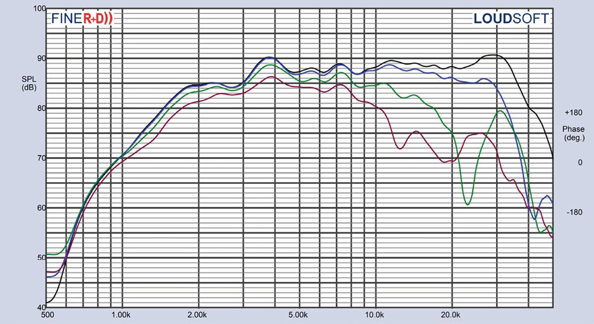
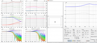
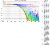
Here's the polar response of the waveguide pictured in my last post.
This performance is pretty darn good, if I do say so myself. It basically sounds the same anywhere in the room.

Here's the vertical polars. As you can see, very narrow. This was by design, I wanted to limit vertical directivity to minimize the energy heading upstairs in my house. (The loudspeakers in my living room literally fire directly into the wall of the master bedroom, which is about the stupidest geometry an architect could possibly come up with.)

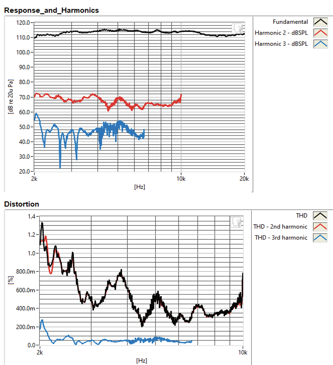
Here's the distortion. Not too shabby I think.
For comparison's sake, check out the distortion and the polars of the SB Acoustics AMT:
An externally hosted image should be here but it was not working when we last tested it.
I was able to achieve superior performance because I masked off part of the AMT diaphragm, in the same manner that BG does with the NEO3 PDR. By masking off part of the diaphragm, you improve the horizontal polars. In the process you lose some efficiency.
Nice results!
I have designed quite a few AMT's. I think those Airborne are made by Hygeia. To say that quality is variable is being charitable. But they do have some interesting designs. And when they are good they are quite good sounding.
This diaphragm is made from Polyester. You can see the breakups in the distortion plot.
Love your horn idea. Has a lot of promise. And I like your adaptation of the PDR idea. I always learn stuff from you. Thanks!

So I've spent most of the weekend buried in ABEC sims, using the super-nifty new feature of ATH that allows us to include the cabinet dimensions when designing a waveguide in ATH.
It confirms something I've suspected for a few years now - we can control beamwidth by manipulating the dimensions of the loudspeaker baffle and the depth of the enclosure.

Here's a crude representation of the idea. On the left is a loudspeaker about the size of a Danley SH50. It's 28" wide. Any wavefront less than twenty eight inches wide (482Hz) will be constrained by the waveguide. On the right is a loudspeaker that's half as wide. Any wavefront less than fourteen inches wide (964Hz) will be constrained by the baffle.
The devil is in the details - and wavefronts that are as much as 1-2 octaves larger will have beamwidth control, because the wavefronts do not dwarf the enclosure. For instance, if the enclosure that's fourteen inches wide radiates a wavefront that is twenty eight inches wide, the CENTER of the wavefront will be reinforced by the baffle while the SIDES of the wavefront will not. This will basically make the CENTER of the wavefront louder than the sides. The net effect is that the wavefront is "shaded." To our ears and our microphone, I don't think we can see a difference between a wavefront shaded by the enclosure, or a wavefront that has it's directivity controlled by a waveguide.
The bottom line: We can probably get away with waveguides that are 2-4x smaller than we've been using IF we design the baffle and enclosure carefully.
If we go this route, this creates a curious problem:
Where do we put the woofer?
I am starting to wonder if we'd get better results putting the woofers on the side or on the back of the enclosure. Similar to the Kii Audio Three.
ABEC is still grinding away as I write this, but from what I can see, it looks like an enclosure that's about 14 inches in diameters is very capable of controlling the beamwidth down to about 200-300Hz as long as the dimensions and baffle shape are right.
Where things get complicated is that if the height of the enclosure is excessive, you get a broadening of the beamwidth in the midrange.

You can see this in this measurement of the JBL 708P from Erins Audio Corner

Any my sim of a comparably sized enclosure shows the same problem.
I think the reason that this is happening is because the baffle is TOO HIGH. In the sim shown, the baffle height is seventeen inches. 794Hz is seventeen inches long. So what's happening is that the tall baffle is broadening the radiation in the midrange.
Maybe I'm splitting hairs here, but I'm not keen on having a frequency response and polar response issue smack dab in the middle of the midrange. Besides the fact that it will change the timber of the loudspeaker, it will also cause a lot of loudspeaker energy to get radiated into the floor and the ceiling in the midrange (because the vertical directivity is so wide at 1khz.)
A few ideas on how to fix it:
Something that seems compelling to me, is a full range source on the front of the loudspeaker enclosure that can play down to about 350Hz. This could be a single full range driver, or something that can approximate it, like a Kef Uni Q or a Unity horn.
Genelec's most expensive offering does this, and I believe it's the highest ranked speaker on the Spinorama tests, as of April 2022.
It confirms something I've suspected for a few years now - we can control beamwidth by manipulating the dimensions of the loudspeaker baffle and the depth of the enclosure.
Here's a crude representation of the idea. On the left is a loudspeaker about the size of a Danley SH50. It's 28" wide. Any wavefront less than twenty eight inches wide (482Hz) will be constrained by the waveguide. On the right is a loudspeaker that's half as wide. Any wavefront less than fourteen inches wide (964Hz) will be constrained by the baffle.
The devil is in the details - and wavefronts that are as much as 1-2 octaves larger will have beamwidth control, because the wavefronts do not dwarf the enclosure. For instance, if the enclosure that's fourteen inches wide radiates a wavefront that is twenty eight inches wide, the CENTER of the wavefront will be reinforced by the baffle while the SIDES of the wavefront will not. This will basically make the CENTER of the wavefront louder than the sides. The net effect is that the wavefront is "shaded." To our ears and our microphone, I don't think we can see a difference between a wavefront shaded by the enclosure, or a wavefront that has it's directivity controlled by a waveguide.
The bottom line: We can probably get away with waveguides that are 2-4x smaller than we've been using IF we design the baffle and enclosure carefully.
If we go this route, this creates a curious problem:
Where do we put the woofer?
I am starting to wonder if we'd get better results putting the woofers on the side or on the back of the enclosure. Similar to the Kii Audio Three.
ABEC is still grinding away as I write this, but from what I can see, it looks like an enclosure that's about 14 inches in diameters is very capable of controlling the beamwidth down to about 200-300Hz as long as the dimensions and baffle shape are right.
Where things get complicated is that if the height of the enclosure is excessive, you get a broadening of the beamwidth in the midrange.
You can see this in this measurement of the JBL 708P from Erins Audio Corner
Any my sim of a comparably sized enclosure shows the same problem.
I think the reason that this is happening is because the baffle is TOO HIGH. In the sim shown, the baffle height is seventeen inches. 794Hz is seventeen inches long. So what's happening is that the tall baffle is broadening the radiation in the midrange.
Maybe I'm splitting hairs here, but I'm not keen on having a frequency response and polar response issue smack dab in the middle of the midrange. Besides the fact that it will change the timber of the loudspeaker, it will also cause a lot of loudspeaker energy to get radiated into the floor and the ceiling in the midrange (because the vertical directivity is so wide at 1khz.)
A few ideas on how to fix it:
- Easiest by far is to make the vertical height of the loudspeaker shorter, but this would require one to put the woofer somewhere else. Like the sides of the enclosure, a la Kii Audio Three.
- Curving the face of the enclosure may help, a la Kef Audio LS50
Something that seems compelling to me, is a full range source on the front of the loudspeaker enclosure that can play down to about 350Hz. This could be a single full range driver, or something that can approximate it, like a Kef Uni Q or a Unity horn.
Genelec's most expensive offering does this, and I believe it's the highest ranked speaker on the Spinorama tests, as of April 2022.
Attachments
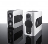
The Grimm Audio speaker is definitely in the ballpark of things I've been looking at. In particular that one could separate the woofer from the midrange and put some "space" around the midrange enclosure, in particular so that diffraction off the midrange enclosure reduces the beamwidth.
To me looks like "main diffraction hump", at least partly. See vertical polars on the attachment which is just an ideal flat source on ideal baffle instead of waveguide on a 3D box.

This diffraction related issue can be completely solved only by having sufficiently large roundovers to make the whole thing approximate a sphere. Any radiator on a baffle, that doesn't have sufficiently large roundover for the wavelength will show this and there is at least one on any physical size loudspeaker object and especially on the vertical axis which has multiple drivers on it making the baffle/object bigger than the transducer supporting longer wavelength and would require bigger roundover. However there are some tricks that help on it if it is a concern, like having smallest structure in comparison to wavelength. In this regard yeah, big waveguide only on the face, then woofers on somewhere else than making extra baffle for the waveguide would reduce the issue but not make it completely away unless the construct was a sphere.
Some thoughts: It is a "tough" issue and really hard to get away if not impossible as we have to have physical size on the loudspeaker. We could make the speaker as big as room to move the problem to room size wavelength, or smaller than highest frequency of interest but that wouldn't leave mucho bass. One would make this completely disappear with midrange wavelength (tens of centimeters) with speaker that is a sphere (enough). Problem is that on multiway speaker we often have two drivers playing same (midrange) baffle sized wavelength and the problem usually spans for pass band of both drivers. We could always use minimal physical size transducer (compared to pass band wavelength) like naked drivers in open baffle configuration and then crossover to smaller one below the diffraction, longer than driver diameter wavelength. This is 3 / 4-way system and eventually at tweeter we'd have to confront the diffraction as we must play past the shorter than transducer size wavelength. Luckily wavelength is short and small roundovers would do. If the open baffle transducers are nulls (90deg to side) of the others there is minimal amount of diffraction, less is just not possible except perhaps with electrostats that don't have driver magnet and structure causing some.
Very good freestanding (or perhaps enclosed) wave guide seem to be able to make diffraction almost disappear (see ATH thread, plenty of examples) but if there is woofer on same baffle the roundovers just have to be big on the vertical dimension, top and bottom lip, bigger than on the sides. We might be able to make system without much diffraction with freestanding waveguide on top of small woofer box, but there are no sims yet, or measurements so it is just a hypothesis currently. Fluid posted some few years back I think, which showed good freestanding waveguide had surprisingly low interaction with a box even if at quite close proximity. Still, the waveguide is probably used only to about wavelengths its mouth diameter and the woofer has to play up to that as well, making both objects size of the wavelength and both interact with each other pass band at the crossover wavelength.
See, tough 🙂 It is all about wavelength and how it interacts with physical objects, and we currently have to have some physical objects to make the sound. OB speaker can be made so that there is (practically) no issues in this regard as explained earlier. Or fullranger on a sphere, or multi-way on relatively big sphere, or just relatively close to sphere, and all with their different set of compromises.
I would think the key to solve good sound for more conventional one-rectangular-box-speaker would be to know how the hearing system works with the sound we see on the graphs. I'm not sure how hearing system processes this and been wondering if all the drivers shared same diffraction fingerprint perhaps the brain can just filter it out effectively, integrate all drivers as one sound source. I've been wondering if this is part why coincident systems have good appeal even though they very rarely take any measures against diffraction. For example the SH50 shows pretty nasty graphs due to "poor" mouth termination but this doesn't seem to matter as the sound is well liked, perhaps the brain just filters it all out? Never hear one so just my speculation. Or the mentioned KEF Ls50, diffraction is nicely distributed and uniform to "all sound sources", even though the diffraction is there perhaps it is less audible as the drivers share it.
edit. the same sim but with minimal baffle, vertical narrowing of the first example is gone.
Attachments
Last edited:
Here lies the nugget for good problem free sound I think, realization that most if not all problems we encounter with loudspeaker builds pretty much all pile up in the midrange, practically sized speaker enclosure dimension wavelengths. All woofers from 15" to 3" are midrange sized, their cone resonances, beaming, all happen at midrange. Enclosures have issues like standing waves, panel resonances, bass reflex pipe resonances, diffraction, all midrange. Then we have at least one crossover somewhere on the midrange on multiway speaker land. Try to cram them all transducers to a physical structure that would have nice pattern to all directions, all with decent SPL and bandwidth requirements for the whole system, everything affects each other being on the proximity. Count in influence of the room, which controls the lows and highs we can quite easily control with a waveguide but the mids between require large objects to impose control over. Worry about visual appeal, size and cost constrains etc. Fun soup 😀I think the reason that this is happening is because the baffle is TOO HIGH. In the sim shown, the baffle height is seventeen inches. 794Hz is seventeen inches long. So what's happening is that the tall baffle is broadening the radiation in the midrange.
Last edited:
Emulating Kii means going active cardioid which will indeed allow you to extend pattern control well below 300 Hz in a narrow enclosure.
Regarding the diffraction hump, I agree with Timu that its inescapable but reducible with roundovers. In my sims, I've found for systems with waveguides, the range coming out of the waveguide is practically immune to the effect. Its the midwoofer you need to take care of. Since I am going active cardioid, the issue is how much of that diffraction hump remains after DSP equalization. Vituix tells me, then I choose roundover to keep it to my target limit. In my latest simulation with 18 mm roundovers, I'm seeing less than 1 db, which shows as a rise of response off axis as the crossover to the CD/waveguide is approached. Given all the other things that will appear when my simulation is given a reality check with a prototype, that seems the point of diminishing returns. Thus I don't think this is much of a problem, at least not with DSP.
I have yet to explore the effect of cabinet depth on the response via ATH/ABEC. but that is on my list of things to do. It would be interesting to know how the depth of the cabinet affects the response off axis...
As a follow on - here is a normalized line chart exported from a copy of timuikku's sim. The high end of this is what you would see after equalization, right? Between 1khz and 3 khzHz, you see a tiny bit of response rise just off axis. This is all that remains of the diffraction hump. A crossover to the waveguide around 1200 Hz or so will remove it almost completely.
Attachments
You could start hereI have yet to explore the effect of cabinet depth on the response via ATH/ABEC. but that is on my list of things to do. It would be interesting to know how the depth of the cabinet affects the response off axis...
https://www.diyaudio.com/community/threads/a-3-way-design-study.376620/post-6831404
Horizontally the freestanding guide doesn't care about the woofer box. Vertically it is a different matter and will look worse, but no worse than a flat baffle, the vertically spaced drivers present the same issues.Fluid posted some few years back I think, which showed good freestanding waveguide had surprisingly low interaction with a box even if at quite close proximity. Still, the waveguide is probably used only to about wavelengths its mouth diameter and the woofer has to play up to that as well, making both objects size of the wavelength and both interact with each other pass band at the crossover wavelength.
- Home
- Loudspeakers
- Multi-Way
- The Nightmare Before Labor Day