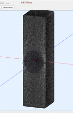
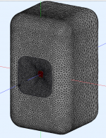
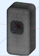
Naturally I was intrigued by the Kef LS60, so I made something similar to it using ATH.
Response isn't "terrible" but the narrow cabinet clearly impacts the directivity. The cabinet that I simmed is something like 20cm wide. The Kef cabinet is 15cm wide iirc. It's a lot smaller than you'd realize, from the pics. It's obviously inspired by the Kef Blade but it's much much smaller.
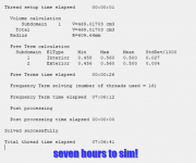
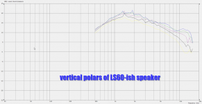
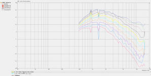
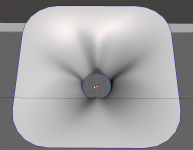
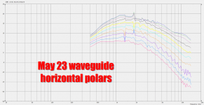
Attached is a sim of the horizontal and vertical directivity. The sim is using a dome tweeter that's basically identical to the SB Acoustics SB26ADC
Horizontal polars are 0-90 degrees and vertical polars are 0-40, same as what Erinsaudiocorner uses.
I think some of the spikes and dips that are very narrow, likely wouldn't manifest in the real world. They're likely due to the perfect symmetry. Basically if you offset the waveguide a bit they'd go away. But I wasn't willing to do that because it would double or quadruple the time to simulate.
The sim took 7+ hours!
Response isn't "terrible" but the narrow cabinet clearly impacts the directivity. The cabinet that I simmed is something like 20cm wide. The Kef cabinet is 15cm wide iirc. It's a lot smaller than you'd realize, from the pics. It's obviously inspired by the Kef Blade but it's much much smaller.
Attached is a sim of the horizontal and vertical directivity. The sim is using a dome tweeter that's basically identical to the SB Acoustics SB26ADC
Horizontal polars are 0-90 degrees and vertical polars are 0-40, same as what Erinsaudiocorner uses.
I think some of the spikes and dips that are very narrow, likely wouldn't manifest in the real world. They're likely due to the perfect symmetry. Basically if you offset the waveguide a bit they'd go away. But I wasn't willing to do that because it would double or quadruple the time to simulate.
The sim took 7+ hours!
Attachments

The KEF LS60 Wireless cabinet is 13 cm wide - not sure how difference it will make to the sims.
They are numerical instabilities combined with a limited number of frequency points, you need to see through those or fix the mesh.I think some of the spikes and dips that are very narrow, likely wouldn't manifest in the real world. They're likely due to the perfect symmetry. Basically if you offset the waveguide a bit they'd go away. But I wasn't willing to do that because it would double or quadruple the time to simulate.
Brute force and CPU cycles is one way to the answer 😉The sim took 7+ hours!
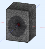
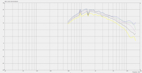
Here's the exact same waveguide from post 141, but this time in a conventionally shaped enclosure. Basically gives you an idea of what happens when the enclosure is tall and narrow, instead of a "monkey coffin."
You'll notice that the tall and narrow enclosure (from post 141) has WIDER vertical beamwidth. (Which is something I do not want.)
In a nutshell, as I see it, the tall narrow enclosure is likely just for cosmetics. IMHO, the "monkey coffin" performs better.
You'll notice that the tall and narrow enclosure (from post 141) has WIDER vertical beamwidth. (Which is something I do not want.)
In a nutshell, as I see it, the tall narrow enclosure is likely just for cosmetics. IMHO, the "monkey coffin" performs better.
Attachments
Yeah and it gets even narrower if you shorten it even more, there seems to be some flat on the front still 🙂 Closing in to a freestanding waveguide. No need for a box.
Problems appear as woofer(s) are added to make a system. A box containing woofers lenghtens again, unless you put them into the waveguide, or sidewalls outside to keep tge baffle minimal. Or buy the freestanding waveguide idea, and utilize separate structure for woofer(s).
Problems appear as woofer(s) are added to make a system. A box containing woofers lenghtens again, unless you put them into the waveguide, or sidewalls outside to keep tge baffle minimal. Or buy the freestanding waveguide idea, and utilize separate structure for woofer(s).
If you want vertical directivity at LF, you need an array. If still not enough, add cardioid features to the array.
Or rationalize that the brain filters out the floor reflection
Or rationalize that the brain filters out the floor reflection
If you want vertical directivity at LF, you need an array. If still not enough, add cardioid features to the array.
Or rationalize that the brain filters out the floor reflection
Yep.
Realized that I'll probably need an MTM with a Unity horn in the center.
I did a lot of tinkering with CBTs, but the Unity solution seems to offer the best treble.
Here's some sims that I did for an MTM that measures about 20" x 12" x 12"
I think the results could be significantly improved by breaking up the symmetry. Which I'll do next.
Attachments


I tried re-doing the enclosure from post 147, but this time with the waveguide offset, with the hope that it would smooth out the frequency response.
It did not.
This leads me to think there's three possibilities:
1) ABEC is exaggerating the peaks and the dips
2) the extremely small diffraction slot in the waveguide is screwing things up
3) Some of the historical data seems to indicate that large waveguides work better than small ones, and perhaps the issue here is the small size of the waveguide.
Here's the config file:
Throat.Diameter = 34 ; [mm]
Throat.Angle = 5 + 17.5 * sin(2*p)^2
Throat.Profile = 1
Length = 44.4 ; [mm]
Slot.Length = 8.5 * cos(2*p)^4
Coverage.Angle = 48
;Coverage.Angle = 50 + 10 * cos(p)^4 + 5 * sin(p)^4
;Coverage.Angle = 50 + 5 * cos(p)^4 + 10 * sin(p)^2
;Term.s = 0.7 + 0.2*cos(p)^2
Term.s = 1.32
Term.n = 4.03
Term.q = 0.996
Source.Contours = {
zoff -2
point p1 4.68 0 2
point p2 0 14 0.5
point p3 1 15 0.5
point p4 0 16 0.5
point p5 0 17 1
cpoint c1 -18.59 0
cpoint c2 0 15
arc p1 c1 p2 1.0
arc p2 c2 p3 0.75
arc p3 c2 p4 0.25
line p4 p5 0
line p5 WG0 0
}
Morph.TargetShape = 1
Morph.FixedPart = 0.6
Morph.Rate = 3
Morph.CornerRadius = 38.1 ; [mm]
Mesh.Enclosure = {
Spacing = 67,149,67,295 ; (left, top, right, bottom) [mm]
Depth = 300
EdgeRadius = 57.15
EdgeType = 1
FrontResolution = 8,8,16,16
BackResolution = 20,20,20,20
}
; -------------------------------------------------------
; Mesh Setting
; -------------------------------------------------------
; ABEC
Mesh.Quadrants = 14
Mesh.AngularSegments = 96
Mesh.LengthSegments = 40
Mesh.CornerSegments = 6
; Fusion 360
;Mesh.AngularSegments = 60
;Mesh.DepthSegments = 20
;Mesh.CornerSegments = 5
Mesh.ThroatResolution = 6.0 ; [mm]
Mesh.InterfaceResolution = 8.0 ; [mm]
Mesh.InterfaceOffset = 5.0 ; [mm]
; -------------------------------------------------------
; ABEC Project Setting
; -------------------------------------------------------
ABEC.SimType = 2
ABEC.f1 = 375 ; [Hz]
ABEC.f2 = 16000 ; [Hz]
ABEC.NumFrequencies = 100
ABEC.MeshFrequency = 1000 ; [Hz]
;ABEC.Abscissa = 1
ABEC.Polars:SPL_H = {
MapAngleRange = 0,90,10
Distance = 2 ; [m]
Offset = 50
}
ABEC.Polars:SPL_V = {
MapAngleRange = 0,40,5
Distance = 2 ; [m]
Offset = 50
Inclination = 90
}
; -------------------------------------------------------
Output.STL = 1
Output.ABECProject = 1
GridExport:f360 = {
ExportProfiles = 0
ExportSlices = 1
Scale = 0.1
}
Report = {
Title = "ls60-ish"
PolarData = "SPL_H"
NormAngle = 10
}
Attachments

Something is wonky there. I've simmed my own SB26 waveguides on a standmount-size speaker and there is none of that jaggedness. Try the source info below. I've validated this by comparing my own measured response of the waveguide on a largish baffle vs the ABEC sim. I also wonder if there isn't a break or something in the mesh causing this?
Source.Contours = {
zoff -1.325
point p1 2.9 0 2.5
point p2 0 13.65 0.5
point p3 1.325 14.975 0.5
point p4 0 16.3 1.0
point p5 0 16.51 1
cpoint c1 -30.675 0
cpoint c2 0 14.975
arc p1 c1 p2 1.00
arc p2 c2 p3 0.75
arc p3 c2 p4 0.25
line p4 p5 0
line p5 WG0 0
}
Source.Velocity = 2
Source.Contours = {
zoff -1.325
point p1 2.9 0 2.5
point p2 0 13.65 0.5
point p3 1.325 14.975 0.5
point p4 0 16.3 1.0
point p5 0 16.51 1
cpoint c1 -30.675 0
cpoint c2 0 14.975
arc p1 c1 p2 1.00
arc p2 c2 p3 0.75
arc p3 c2 p4 0.25
line p4 p5 0
line p5 WG0 0
}
Source.Velocity = 2
A break in the sim - that makes a lot of sense.
Something I've noticed when you mess around with the waveguide to create something similar to the JBL image control waveguides, is that you end up with a waveguide face that isn't perfectly flat. That creates issues when using ATH to integrate with an enclosure.
Something I've noticed when you mess around with the waveguide to create something similar to the JBL image control waveguides, is that you end up with a waveguide face that isn't perfectly flat. That creates issues when using ATH to integrate with an enclosure.
There is some numerical instability but I suspect part of the underlying ripple is real and comes from the shape. The knuckles in a North South East West arrangement will not spread the diffraction effectively and concentrate it more on axis which is seen in the result.This leads me to think there's three possibilities:
1) ABEC is exaggerating the peaks and the dips
2) the extremely small diffraction slot in the waveguide is screwing things up
3) Some of the historical data seems to indicate that large waveguides work better than small ones, and perhaps the issue here is the small size of the waveguide.
If there was a hole in the mesh (big enough to matter) the results would be total garbage.
Empirically I have found that using an interface with smaller waveguides in 4pi simulations is tricky to get right, and most often it is better to treat everything as exterior radiation and do away with the interface. There might be settings to achieve that directly in Ath but it is easy enough to manually change the solving file.
Empirically I have found that using an interface with smaller waveguides in 4pi simulations is tricky to get right, and most often it is better to treat everything as exterior radiation and do away with the interface. There might be settings to achieve that directly in Ath but it is easy enough to manually change the solving file.
I wish I understood what that means 🙁
OK we're FINALLY starting to get close to a practical solution.
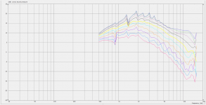
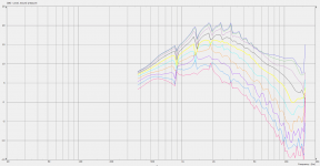
Attached is a sim of a very basic enclosure, a box with rounded edges that measures about 16" x 16" x 12"
As noted in previous posts and threads, the geometry of the box itself tends to impact the beamwidth. Basically you can use a waveguide that's much smaller than you might expect, if you manipulate the dimensions of the box.
And we see that in these sims. 400Hz is almost a meter long, but we see directivity control all the way down to 400Hz in these sims, largely due to juggling the dimensions of the box and the waveguide.
I'm going to try again, this time with a smaller box.
Attachments
You are square there. Have you tried axisymmetric? I've had good results with it. at least you will get an answer quickly
ABEC/AKABAK models in Sub Domains where the radiation is defined as either interior or exterior, an interface bridges the gap between the two.I wish I understood what that means 🙁
In an infinite baffle simulation the interior is everything behind the baffle and exterior is everything in front, the interface divides the two so they are solved separately.
In a shallow waveguide there is very little benefit from using an interface and often it causes problems to get it right.
It is possible to assign all the elements to the external subdomain and get rid of the interface which also saves however many elements the interface is made up of.
If you want to attach one of your ABEC projects I can edit the solving file to make it external for you, it is quite simple but easier to do than explain.
I tried to cover that a bit in the documentation, see pages 13 and 43: http://www.at-horns.eu/release/Ath-4.8.2-UserGuide.pdf#page=13
In a project that has already been created you can adjust it like this in the solving.txt file, the interface has been disabled by putting off in front of it as has the second subdomain and infinite baffle ( you can use // but then you have to do it on every line where off turns everything off until a line break)
By making subdomain 1 exterior and making sure all elements are linked to subdomain 1
By making subdomain 1 exterior and making sure all elements are linked to subdomain 1
Code:
SubDomain_Properties
  SubDomain=1; ElType=Exterior

off Elements "Interface1"
  SubDomain=1,2; MeshFileAlias="M2"
  101 Mesh Include 14

off SubDomain_Properties
  SubDomain=2; ElType=Exterior

Elements "WG1"
  SubDomain=1; MeshFileAlias="M2"
  102 Mesh Include 5,11

Elements "Drive_25"
  SubDomain=1; MeshFileAlias="M1"
  Shift=0mm,0mm,1.325mm
  103 Mesh Include drive_25

Driving "Source_25"
  RefElements="Drive_25"; DrvGroup=1001; Direction=z

Elements "Drive_75"
  SubDomain=1; MeshFileAlias="M1"
  Shift=0mm,0mm,1.325mm
  104 Mesh Include drive_75

Driving "Source_75"
  RefElements="Drive_75"; DrvGroup=1002; Direction=z

Elements "Drive_100"
  SubDomain=1; MeshFileAlias="M1"
  Shift=0mm,0mm,1.325mm
  105 Mesh Include drive_100

Driving "Source_100"
  RefElements="Drive_100"; DrvGroup=1003; Direction=z

off Infinite_Baffle
Subdomain=1; Position=z offset=19mmWhen I named this topic "Nightmare Before Labor Day", I didn't realize it would be 2022 or 2023 lol
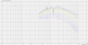
But I seem to be getting close to something that works.
Attached is what's been working well for me.
Here's some things that I found which might help out with your Unity horn projects:
Attached are pics of the simulated response.
The waveguide itself measures 10.47" x 10.47"
The enclosure measures 406mm x 380mm x 300mm
The roundover is 3.5" in diameter
Here's the config file:
Throat.Diameter = 34 ; [mm]
Throat.Angle = 5 + 17.5 * sin(2*p)^2
Throat.Profile = 1
Length = 76.2 ; [mm]
Slot.Length = 5 * cos(2*p)^4
Coverage.Angle = 43.5 + 7 * sin(2*p)^8
;Coverage.Angle = 50 + 10 * cos(p)^4 + 5 * sin(p)^4
;Coverage.Angle = 50 + 5 * cos(p)^4 + 10 * sin(p)^2
;Term.s = 0.7 + 0.2*cos(p)^2
Term.s = 1.32
Term.n = 4.03
Term.q = 0.996
Source.Contours = {
zoff -1.325
point p1 2.9 0 2.5
point p2 0 13.65 0.5
point p3 1.325 14.975 0.5
point p4 0 16.3 1.0
point p5 0 16.51 1
cpoint c1 -30.675 0
cpoint c2 0 14.975
arc p1 c1 p2 1.0
arc p2 c2 p3 0.75
arc p3 c2 p4 0.25
line p4 p5 0
line p5 WG0 0
}
Source.Velocity = 2
Morph.TargetShape = 1
Morph.FixedPart = 0.75
Morph.Rate = 3
Morph.CornerRadius = 38.1 ; [mm]
Mesh.Enclosure = {
Spacing = 57.16,70.2,57.15,70.2 ; (left, top, right, bottom) [mm]
Depth = 300
EdgeRadius = 44.45
EdgeType = 1
FrontResolution = 8,8,16,16
BackResolution = 20,20,20,20
}
; -------------------------------------------------------
; Mesh Setting
; -------------------------------------------------------
; ABEC
;Mesh.Quadrants = 14
Mesh.Quadrants = 1
Mesh.AngularSegments = 96
Mesh.LengthSegments = 40
Mesh.CornerSegments = 6
; Fusion 360
;Mesh.AngularSegments = 60
;Mesh.DepthSegments = 20
;Mesh.CornerSegments = 5
Mesh.ThroatResolution = 6.0 ; [mm]
Mesh.InterfaceResolution = 8.0 ; [mm]
Mesh.InterfaceOffset = 5.0 ; [mm]
; -------------------------------------------------------
; ABEC Project Setting
; -------------------------------------------------------
ABEC.SimType = 2
ABEC.f1 = 400 ; [Hz]
ABEC.f2 = 14000 ; [Hz]
ABEC.NumFrequencies = 100
ABEC.MeshFrequency = 1000 ; [Hz]
;ABEC.Abscissa = 1
ABEC.Polars:SPL_H = {
MapAngleRange = 0,90,10
Distance = 2 ; [m]
Offset = 50
}
ABEC.Polars:SPL_V = {
MapAngleRange = 0,40,5
Distance = 2 ; [m]
Offset = 50
Inclination = 90
}
; -------------------------------------------------------
Output.STL = 1
Output.ABECProject = 1
GridExport:f360 = {
ExportProfiles = 0
ExportSlices = 1
Scale = 0.1
}
Report = {
Title = "MTM_may_23_2022"
PolarData = "SPL_H"
NormAngle = 10
}
But I seem to be getting close to something that works.
Attached is what's been working well for me.
Here's some things that I found which might help out with your Unity horn projects:
- Asymmetrical waveguides really don't seem to work, as Danley has observed.
- Every time I tried various combinations of enclose size and waveguide size, I found the waveguide getting smaller and smaller and smaller. In the pro audio world we see a lot of waveguides where the waveguide reaches the edge of the enclosure. This doesn't seem to work well. As @mabat has demonstrated in his projects, waveguides really seem to need a roundover. I'm not sure I can see a scenario where I'll make a waveguide without a roundover from now on. So if you have a fixed amount of space for the baffle, it's going to reduce the size of your waveguide quite a bit. For instance, if your enclosure is limited to 400mm x 400mm your waveguide size will be fairly small. This is because you should really use a roundover.
Attached are pics of the simulated response.
The waveguide itself measures 10.47" x 10.47"
The enclosure measures 406mm x 380mm x 300mm
The roundover is 3.5" in diameter
Here's the config file:
Throat.Diameter = 34 ; [mm]
Throat.Angle = 5 + 17.5 * sin(2*p)^2
Throat.Profile = 1
Length = 76.2 ; [mm]
Slot.Length = 5 * cos(2*p)^4
Coverage.Angle = 43.5 + 7 * sin(2*p)^8
;Coverage.Angle = 50 + 10 * cos(p)^4 + 5 * sin(p)^4
;Coverage.Angle = 50 + 5 * cos(p)^4 + 10 * sin(p)^2
;Term.s = 0.7 + 0.2*cos(p)^2
Term.s = 1.32
Term.n = 4.03
Term.q = 0.996
Source.Contours = {
zoff -1.325
point p1 2.9 0 2.5
point p2 0 13.65 0.5
point p3 1.325 14.975 0.5
point p4 0 16.3 1.0
point p5 0 16.51 1
cpoint c1 -30.675 0
cpoint c2 0 14.975
arc p1 c1 p2 1.0
arc p2 c2 p3 0.75
arc p3 c2 p4 0.25
line p4 p5 0
line p5 WG0 0
}
Source.Velocity = 2
Morph.TargetShape = 1
Morph.FixedPart = 0.75
Morph.Rate = 3
Morph.CornerRadius = 38.1 ; [mm]
Mesh.Enclosure = {
Spacing = 57.16,70.2,57.15,70.2 ; (left, top, right, bottom) [mm]
Depth = 300
EdgeRadius = 44.45
EdgeType = 1
FrontResolution = 8,8,16,16
BackResolution = 20,20,20,20
}
; -------------------------------------------------------
; Mesh Setting
; -------------------------------------------------------
; ABEC
;Mesh.Quadrants = 14
Mesh.Quadrants = 1
Mesh.AngularSegments = 96
Mesh.LengthSegments = 40
Mesh.CornerSegments = 6
; Fusion 360
;Mesh.AngularSegments = 60
;Mesh.DepthSegments = 20
;Mesh.CornerSegments = 5
Mesh.ThroatResolution = 6.0 ; [mm]
Mesh.InterfaceResolution = 8.0 ; [mm]
Mesh.InterfaceOffset = 5.0 ; [mm]
; -------------------------------------------------------
; ABEC Project Setting
; -------------------------------------------------------
ABEC.SimType = 2
ABEC.f1 = 400 ; [Hz]
ABEC.f2 = 14000 ; [Hz]
ABEC.NumFrequencies = 100
ABEC.MeshFrequency = 1000 ; [Hz]
;ABEC.Abscissa = 1
ABEC.Polars:SPL_H = {
MapAngleRange = 0,90,10
Distance = 2 ; [m]
Offset = 50
}
ABEC.Polars:SPL_V = {
MapAngleRange = 0,40,5
Distance = 2 ; [m]
Offset = 50
Inclination = 90
}
; -------------------------------------------------------
Output.STL = 1
Output.ABECProject = 1
GridExport:f360 = {
ExportProfiles = 0
ExportSlices = 1
Scale = 0.1
}
Report = {
Title = "MTM_may_23_2022"
PolarData = "SPL_H"
NormAngle = 10
}
Attachments
![2022-05-27 22_17_48-VacsViewer - (new) - [Converted from PolarMap_SPL_V].png](/community/data/attachments/966/966650-9b271b3cba737fe426615a5c8e5bbb8a.jpg?hash=mycbPLpzf-)
You can easily try to remove the interface by setting "Mesh.SubdomainSlices =" (exactly as stated).
- Home
- Loudspeakers
- Multi-Way
- The Nightmare Before Labor Day