if you have it as that - IRFP150 on neg phase and IRFP240 on positive phase, with (measly) sum Iq 1A, 2nd is dominant and pretty high
and it is not unreal to expect 0.1% THD@1W that way
pretty much all is important do you like sound or not ....... and it is nice you can alter it for your liking
though, whichever approach you take - symmetry, or spiled syummetry, with proper Iq, THD is going to be lower
personally, I wouldn't go bellow 2A sum channel Iq, but that's your amp......
so that's it
forgetabaut THD level, just voice it for your liking and enjoy
I mean, be happy that you can do that with this topology - invoking 2nd, choosing which polarity of same etc.
forgetabaut THD level, just voice it for your liking and enjoy
I mean, be happy that you can do that with this topology - invoking 2nd, choosing which polarity of same etc.
What I wanted to say is that the sound is so good that I don`t even notice the thd is there.Even if on the fft at this levels the thd of boo is pretty high the sound is terrific.


Thought provoking isn't it. Then how does an F4 bridged with Old Soul sounds and later on ..... 🙂 The journey shall go on.

What I wanted to say is that the sound is so good that I don`t even notice the thd is there.
still happy, did no changes in OS parts?
The last week I got a true rms multimeter and had the chance for a few days to pump up a bit the volume too.
Since I built the amps I used IP as my pre. This gives 4-5wrms and peaks of 16w. It sounds nice and at max volume I don’t notice the thd like I said in the past and it’s loud enough.
Curious how the bba3 pre sounds now when I was familiar with the sound of IP, I replaced the gain pcbs and started the listening.
Don’t know if it’s an illusion from the extra gain but the speakers seem to go lower and also the maximum power now is wild.
I would like to try a different set of outputs, the Toshiba 2SK3497 / 2SJ618.
I seen these have low thd and I want to hear this version too.
I want to try also a version with lu1014 but for this one I`m still working to the cascode pcb
So yes still happy and no changes in OS until now.
Attachments
The story goes on!
Because I like the sound I hear with the actual mosfet combo I use, I want to try the LU1014 and see how it sounds.
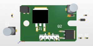
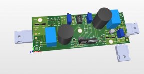
The alu pcb idea in post #193 seems not good for a long capacitor life(thx to ZM advice from another thread) so I went ahead and modified the errors I had in r0 and added also the cascode for the jfet.
The LU1014 I have are from Nelson stash and are already on aluminium pcbs from the same gb with the jfets.
Will be ordering the pcbs the next days, till then I am open to suggestions if any.
😎
Because I like the sound I hear with the actual mosfet combo I use, I want to try the LU1014 and see how it sounds.
The alu pcb idea in post #193 seems not good for a long capacitor life(thx to ZM advice from another thread) so I went ahead and modified the errors I had in r0 and added also the cascode for the jfet.
The LU1014 I have are from Nelson stash and are already on aluminium pcbs from the same gb with the jfets.
Will be ordering the pcbs the next days, till then I am open to suggestions if any.
😎
Attachments

you'll most likely get 2nd dominant right from the box, but which polarity, can't tell without proper sim and I have no time for that in present time
though, easy to revert speakers phase on output terminals, so phase really not being that important
though, easy to revert speakers phase on output terminals, so phase really not being that important
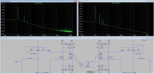
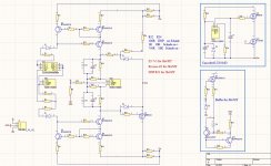
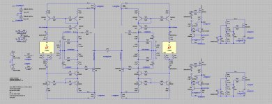
Yesterday I found a spice model for lu1014 and this encouraged me to go ahead and simulate the circuit.
First thing that I discovered is that with dn2540 it’s difficult to set the absolute offset to 0v, you have to modify some resistors(the 4.3k ones that are used to set the DC offset)on the input side of the amp to have a big ratio between them.
Instead if using the irf510 it works with the standard 4.3k resistors and 5k pot.
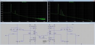
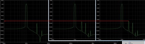
Now to introduce some 2nd hd all you need to do is play with the vds of lu1014.
I am attaching a screenshot with the lu vds set for the lowest thd and higher thd levels.
Seems a lot of fun ahead
First thing that I discovered is that with dn2540 it’s difficult to set the absolute offset to 0v, you have to modify some resistors(the 4.3k ones that are used to set the DC offset)on the input side of the amp to have a big ratio between them.
Instead if using the irf510 it works with the standard 4.3k resistors and 5k pot.
Now to introduce some 2nd hd all you need to do is play with the vds of lu1014.
I am attaching a screenshot with the lu vds set for the lowest thd and higher thd levels.
Seems a lot of fun ahead
Attachments
- Home
- Amplifiers
- Pass Labs
- The marriage