Hello guys,
I`ve been dreaming for a long time on a nice balanced preamp that can drive directly a power follower.
Lately @Zen Mod offered both the nice preamp, the Iron Pre, and also a lot of power followers from which one in particular caught my attention and that is Plethora of Pinjatas .
Slowly but steady I managed to draw a pcb for the IP and mount it in my UGS Pre, obviously the idea was implemented with the help of Zen Mod.
Now I want to start drawing the pcb(s) with the OS of Plethora of Pinjatas but not being sure if it`s going to work I asked Zen Mod about it and on his advice I started this thread.
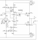
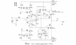
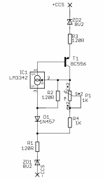
So again slowly(I have close to 10 years since I dream about this) I started to copy the schematic of Plethora of Pinjatas OS and to make the pcb.
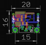
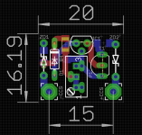
To mention that the dimension between the holes of the mosfets in my case is 15cm, I don`t use the standard UMS.
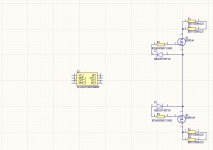
If I got it right I need 2x OSes, to the input of the first OS(R125) I will connect the positive output of the preamp and to the input of the second OS(R125) I will connect the negative output of the preamp. From the positive OS I will take the + signal for the speaker, from the negative OS I will take the - signal for the speaker, correct?
Now how can I adjust the offset? Is it ok to use same config as Sissysit 42? What will happen if I have the preamp dc coupled and the input of the OS(R125) is not at 0V?
I`ve been dreaming for a long time on a nice balanced preamp that can drive directly a power follower.
Lately @Zen Mod offered both the nice preamp, the Iron Pre, and also a lot of power followers from which one in particular caught my attention and that is Plethora of Pinjatas .
Slowly but steady I managed to draw a pcb for the IP and mount it in my UGS Pre, obviously the idea was implemented with the help of Zen Mod.
Now I want to start drawing the pcb(s) with the OS of Plethora of Pinjatas but not being sure if it`s going to work I asked Zen Mod about it and on his advice I started this thread.
So again slowly(I have close to 10 years since I dream about this) I started to copy the schematic of Plethora of Pinjatas OS and to make the pcb.
To mention that the dimension between the holes of the mosfets in my case is 15cm, I don`t use the standard UMS.
If I got it right I need 2x OSes, to the input of the first OS(R125) I will connect the positive output of the preamp and to the input of the second OS(R125) I will connect the negative output of the preamp. From the positive OS I will take the + signal for the speaker, from the negative OS I will take the - signal for the speaker, correct?
Now how can I adjust the offset? Is it ok to use same config as Sissysit 42? What will happen if I have the preamp dc coupled and the input of the OS(R125) is not at 0V?
Attachments
Hold your horses, will post something for you tonight
I can fulfill all requirements, and you'll need to fulfill just one - to tap M3 holes according to my pcb arrangement
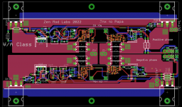
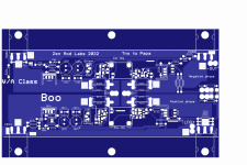
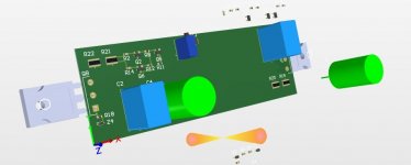
teaser enclosed, work in progress
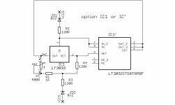
it'll have offset setting per phase, Iq setting CCS Daughterboards ( so you can choose either LT3092 or LM334) and all blingies - choice of pure MOS or Schade MOS; heck, you can even use SIT up, instead of Schade, I don't care
can be used either as single bridge channel or as two independent channels, but with common PSU for both
I can fulfill all requirements, and you'll need to fulfill just one - to tap M3 holes according to my pcb arrangement
teaser enclosed, work in progress
it'll have offset setting per phase, Iq setting CCS Daughterboards ( so you can choose either LT3092 or LM334) and all blingies - choice of pure MOS or Schade MOS; heck, you can even use SIT up, instead of Schade, I don't care
can be used either as single bridge channel or as two independent channels, but with common PSU for both
Attachments
Hmm you always have the best cards in your hands ")
To be honest I took the route to draw my own pcbs because I don’t have the hardware to drill and tap new holes in the heatsinks, I need a column drill that I can’t manage to get.
The heatsinks that my monoblocks have are simply to small to be able to accommodate your pcb, I mean a heatsink can cool ~70w and this is good only for half of your pcb.
I will draw a pcb for - and one for + and each will go on it’s own heatsink.
I hope I don’t offend you in anyway with this.
The good thing is that I am good at copying stuff from others so in this case I will divide your pcb in 2 and copy it.
For the components like 3092 I am choosing the footprint that I find available on mouser.
Take your time, no hurry. I am slow anyway and thanks for being around!
I'll post my files, schm and gerbers and whatnot, then you can do whatever you want
have no time to make custom package for you and anyway this iteration is more Kosher than you need, so possible to make more Greedy Boyz happy
btw - for few taps all you really need is accudrill, few drill-bits and tap and tiny amount of gentle approach
sometimes when I'm lazy and have just few to tap, I'm not even moving from chair - my bench drill being outa my electronic workshop, so just taking accudrill from drawer
good grease/oil is must have and pretty much everyone is having bicycle pump to blast holes
and shooting through-holes between sink ribs became habit with time, much easier than blind holes/taps
Now that I learned to draw my pcbs you want to take the joy away from me?to make custom package for you
)You did make custom package for me only that you are not aware of it. Thanks!
Didn’t have problems when tapping but when drilling, drilling straight it’s simply not for me. I tried a lot of times in the past at work and had success a few times . This made me use only the column drill and take the hard way only when I was at work outside and the column drill was away.
Now that I have also the excuse that your pcb doesn’t fit thermally…I went ahead also with the schematic…in one word I am not so greedy(but the most greedier)
question - in case that you have separately two pcbs - one for positive phase and one for negative - practically this one cut in half, same size as regular channels in my amps - would that be adequate for your hsinks arrangement?
I mean, if I did this, cutting this in two is trivial
I mean, if I did this, cutting this in two is trivial
........
Didn’t have problems when tapping but when drilling, drilling straight it’s simply not for me. I tried a lot of times in the past at work and had success a few times . This made me use only the column drill and take the hard way only when I was at work outside and the column drill was away.
.......
you can try using so called drilling jigs or drilling guides
I am using 2 heatsinks on each channel(300x160x40 mm), each one doing ~70w(22v/3.2a) right now. At 60c with 25c room temp they are a bit on the hot side.practically this one cut in half, same size as regular channels in my amps - would that be adequate for your hsinks arrangement?
At 22v one phase of Boo will do ~75w, this already means I have to lower a bit the bias and I intend to go to 1.3a so yes I do need to make 2 pcbs.
The amps are a tight fit inside(20cm wide) with the trafo mounted vertically in the front followed by some big rifa peh and some motor run caps. The mosfet that comes in the front is close to the transformer. If I try to use a larger pcb I will have the mosfet near the trafo this being another reason that forces me to use the actual holes that I have and draw the pcbs.
I would gladly take yours but in this case I have to insist on drawing some to fit my needs.
Attachments
far from that I'm being against you drawing your own - best way of having fun and being proud and happy
just asked - again, cutting them in half is trivial now, would that be good enough

btw. Boo will sing with 1A Iq per phase, no worries ....... especially if you intend to use just part of possible power
you can go lower with rails - say 16-18Vdc; 15Vac secondaries will give you that, with 2A sum Iq, that's 72W of heat for entire channel
well, you can go even lower with Iq ..... 0A7, why not .....
just asked - again, cutting them in half is trivial now, would that be good enough
btw. Boo will sing with 1A Iq per phase, no worries ....... especially if you intend to use just part of possible power
you can go lower with rails - say 16-18Vdc; 15Vac secondaries will give you that, with 2A sum Iq, that's 72W of heat for entire channel
well, you can go even lower with Iq ..... 0A7, why not .....
With low impedance speakers I suppose it`s wise to lower the rails and increase iq. To lower the rails I have 2 ways, I insert a resistor right after the bridge and the first cap(I have crc psu) or remove the resistor from the crc and insert a cap multiplier (or a chip voltage regulator) but this one needs drilling and tapping.

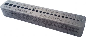
you can try using so called drilling jigs or drilling guides
I have successfully drilled many holes in heat sinks for tapping using an electric hand drill and a drill guide.
I have one of these:
Big Gator Tools Drill Guide
Works great for me. I centre punch a large dimple at the hole location, hold the drill guide down with the fingers or thumb of one hand, and hold the drill with the other hand.
Lately my drill bit for the holes that I need for M3 screws was getting dull and drilling was difficult. I bought some new bits and what a difference. Each hole took less than minute, and didn't require much effort.
I also use the drill guide to locate and start the tap in a vertical position.
Attachments
here it is, Boo
post #6
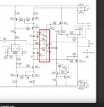
error around ZD203, one trace shorted
will rectify and repost tomorrow
post #6
error around ZD103, one trace shorted
will rectify and repost tomorrow
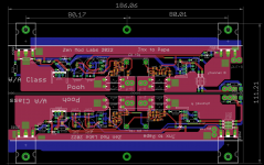
fixed error with shorted trace of ZD103, proper Gerbers enclosed
while I'm here, interested in specialspecialschultzsch iteration?

Attachments
what difference is between Pooh and Boo?while I'm in Office .....
I guess I will search for something when I`ll be really forcedI have successfully drilled many holes
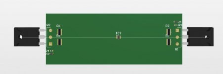
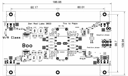
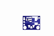
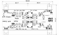
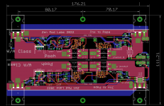
I went asleep a bit later yesterday night, please see attached photo. I see that you have 160mm distance between the mosfet holes, I have 150mm, it is easy to leave the mosfet pins 5mm longer and use these pcbs also with the standard UMS. A similar thing can be done with your pcbs , if you bend the upper part of each mosfet 5mm toward the middle you get 150mmwhile I'm here
Attachments
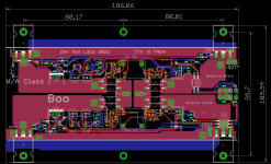
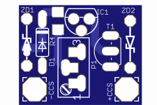
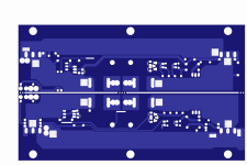
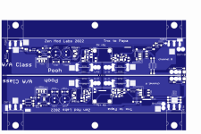
-Boo is one whole pcb, PSU pads common for both phases;
-Pooh is breakable in two halves, separate PSU pads for each halve/phase, exactly to allow positioning of them on separate heatsinks;
-look better at distance between two mosfets on pic in #18
of course, I welcome your decision to make your own pcb, it was only my own fun to make it while I still wasn't eager to sleep
- Home
- Amplifiers
- Pass Labs
- The marriage