SJEP or SJDP?
edit: judging by "E" on type string, it is SJEP, so enhancement part, normally Off, demanding positive Ugs to conduct
contrary to LU, which is depletion mode part, normally ON, demanding negative Ugs to control conduction
yes, it can be used instead of [LU+Cascode], with next changes:
how it will sing ? most likely similar to LU, but with gigher THD, simply because SJEP isn't having that wild xconductance, as cascoded LU is having
edit: judging by "E" on type string, it is SJEP, so enhancement part, normally Off, demanding positive Ugs to conduct
contrary to LU, which is depletion mode part, normally ON, demanding negative Ugs to control conduction
yes, it can be used instead of [LU+Cascode], with next changes:
- level shifter mosfet change form IRF510 to DN2530 or DN2540 (TO220 case)
- change of level shifter resistor value; can't say to what value from top of my head, but easily calculable, if needed
how it will sing ? most likely similar to LU, but with gigher THD, simply because SJEP isn't having that wild xconductance, as cascoded LU is having
Last edited:
Sjep.
I will keep the actual design with the lu1014 and will try something different with these… I guess
I will keep the actual design with the lu1014 and will try something different with these… I guess
I have 3pcs that are very close matches but the 4th is a bit away at 75mV vgs difference.
Looking around I seen the f6 circuit that adjusts easily the vgs of the sjeps, I could use the good matches on the bottom where is more criticat to have them matched and on the upper position the mismatched ones.
Looking around I seen the f6 circuit that adjusts easily the vgs of the sjeps, I could use the good matches on the bottom where is more criticat to have them matched and on the upper position the mismatched ones.
75mV is practically nothing
and - for F6, if you're opting for symmetry, upper half is of same importance as lower half
though, if opting/thinking about symmetry, only way to get that is having parts matched by xconductance..... Ugs not being exactly measure of dynamic behavior of part
though--though - who cares about symmetry
read Mosfet Testing article on FW site, there is your know-how
difference being ( vs. IRFP series shown in article) is that SJEP are having roughly 1/3 of Ugs, but that's trivial
difference being ( vs. IRFP series shown in article) is that SJEP are having roughly 1/3 of Ugs, but that's trivial
It took me a few days to measure these.
In the note I have written the vgs, gm and id on each line.
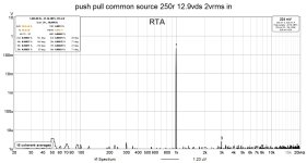
70mv vgs difference is not much when driven from common source at 16ma and 250r drain resistor, just a few ohms. So now I understand why you said that 70mV it’s not much, for that low rd variation the common source doesn’t change much it’s thd.
Discovering how to measure the gm I started first with other parts like the small k170/j74 that I need for a future blowtorch preamp.
It was a nice experiment to see how low thd I could get for a simple push pull common drain/source by tweaking the gm, even 10x lower.
So I learned a new lesson, my semis have to be close in spec to the ones in the original schematic if I want to get same results or I have to adjust the schematic to my semis. Simple as that but it worths it.
I had a lot of fun these days
In the note I have written the vgs, gm and id on each line.
70mv vgs difference is not much when driven from common source at 16ma and 250r drain resistor, just a few ohms. So now I understand why you said that 70mV it’s not much, for that low rd variation the common source doesn’t change much it’s thd.
Discovering how to measure the gm I started first with other parts like the small k170/j74 that I need for a future blowtorch preamp.
It was a nice experiment to see how low thd I could get for a simple push pull common drain/source by tweaking the gm, even 10x lower.
So I learned a new lesson, my semis have to be close in spec to the ones in the original schematic if I want to get same results or I have to adjust the schematic to my semis. Simple as that but it worths it.
I had a lot of fun these days
Attachments
-
 02EDC39D-1C58-4556-AA2C-E350F9A797AD.jpeg820.8 KB · Views: 186
 -
 1CD0E3F4-A5DA-4BEC-85B8-A876E2637EA9.jpeg55.6 KB · Views: 186
 -
 C83B5212-F989-4CA8-A7E0-B38A0E65A671.jpeg55.4 KB · Views: 137
 -
 04D99507-51AA-4664-A5E2-36CB7C3B3E2A.jpeg55.4 KB · Views: 132
 -
 A35FDE93-67B7-46F2-A978-FEFCB68B210E.jpeg58.6 KB · Views: 131
 -
 1BA2CB2F-7A6D-4044-8EE9-C1C82E1C7C06.jpeg130.1 KB · Views: 174
so, just write some factual comparison, between cascoded LU and SJEP, in place of upper OS part
say, THD numbers and then say something about listening differences, if you had enough time to catch that
I mean - easier to write these numbers than for us to compare graphs .........
do not forget to note exact Iq for said measurements
edit: still at first morning coffee, now I see that I have no slightest clue what you did show on graphs
maybe I'll catch that later
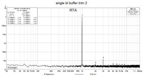
I don’t know yet what way to go with the sjeps. I only measured them.
The graphs are for a simple k170/j74 buffer.
The graphs are for a simple k170/j74 buffer.
aha, now's clear
did ton of chores in a meantime, coffee cold now, didn't had time to finish it
rare occasion, I'm doing my best to have at least first morning coffee (whenever that morning is) in peaceful and lazy way

did ton of chores in a meantime, coffee cold now, didn't had time to finish it
rare occasion, I'm doing my best to have at least first morning coffee (whenever that morning is) in peaceful and lazy way
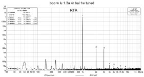
Since you asked.. the boo does a little better.
First thd was like in the first attachment, 1a bias.
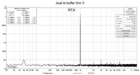
I increased a bit the current through the os from 1a to 1.3a which lowered the 3rd with 50%, this was a good start to try again to tweak the second.
Because I can’t create enough mismatch by altering the vds of the LUs I can’t set to have the 2nd 2x the 3rd so I went for the 2nd 1/2 of the 3rd.I could adjust the polarity so I went for negative.
I didn’t do a screenshot for the config I chosen.
If I go for 1.6a bias I can play better with this mismatch because the 3rd will be lower and maybe there I get the chance to get what I want.
If until now it was fun to solder… now I discovered that it‘s more fun to tweak 😁
First thd was like in the first attachment, 1a bias.
I increased a bit the current through the os from 1a to 1.3a which lowered the 3rd with 50%, this was a good start to try again to tweak the second.
Because I can’t create enough mismatch by altering the vds of the LUs I can’t set to have the 2nd 2x the 3rd so I went for the 2nd 1/2 of the 3rd.I could adjust the polarity so I went for negative.
I didn’t do a screenshot for the config I chosen.
If I go for 1.6a bias I can play better with this mismatch because the 3rd will be lower and maybe there I get the chance to get what I want.
If until now it was fun to solder… now I discovered that it‘s more fun to tweak 😁
Attachments

well, except for contemplation about behavior and trends** in particular sub-assemblies, we can't really compare small JFet buffer and OS DEF stage
*in context of personal preferences, awareness of trends is important; "do I like more dominant 2nd or 3rd, which phase of it I like more?"
so, nature important, quantitative numbers not so
*in context of personal preferences, awareness of trends is important; "do I like more dominant 2nd or 3rd, which phase of it I like more?"
so, nature important, quantitative numbers not so
In both gm is implied…so what I seen interesting on the small one I tried to apply on the bigger one 😁we can't really compare small JFet buffer and OS DEF stage
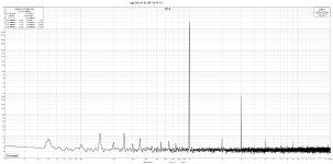
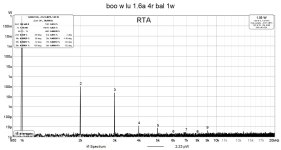
Now I raised the bias to 1.6a and adjusted everything accordingly
I will try to get same thd numbers but at a lower OS bias and adjusting other things.
Edit
*in context of personal preferences, awareness of trends is important; "do I like more dominant 2nd or 3rd, which phase of it I like more?"
I’m just trying to find out this.
Attachments
Last edited:
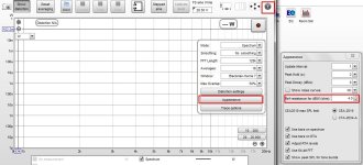
Maybe a bit OT, but why is the FFT Y-axis scale in Watt (power, W)? Does REW know your load resistance? Does THD calculate correctly considering that the power is proportional to the square of the voltage?
I checked with the dmm and the levels were the same(soundcard and dmm)
Firat I checked to see where I can set the load impedance in REW but didn’t managed to find nothing so I used the dmm.
Firat I checked to see where I can set the load impedance in REW but didn’t managed to find nothing so I used the dmm.
Today I noticed one interesting thing.
When I built the mosfet version of boo I did 2 measurements at 1W and 1khz. One was with the speaker(as load) that has 7-8ohms at 1khz and the other one with a 4ohm resistive load. The 3rd with the speaker was 6x lower than with the resistive load.
Obviously when I built the boo with lu I measured again the thd at 1W/1khz but this time only into the resistive load and compared the result to the mosfet version which was using the speaker as load.
Actually both the lu version and the mosfet version have the same level of 3rd into my resistive load.
well, you either have all factors always same, or you can count off any comparison

I found out these days that when I power this ops(the lu version) with smps it oscillates as soon as I connect the input hot wire, works perfectly ok with linear ps.here it is, Boo
I increased R102 from 33r to 1k which solved the problem.
- Home
- Amplifiers
- Pass Labs
- The marriage