I didn’t test them yet for the gate leakage but if this it’s below a certain level can I omit the buffer in front?
No pain, no gain. Everybody needs to pay the cost in learning a lesson, hopefully releasing as little magic smoke as possible. 
I had completely ignored that the buffer is used also for setting the gate voltage of the sit that now doesn’t need to be in a certain range to have the circuit working. I don’t have my sits vgs in that range anyway so I will need it.what is better
If I remember correctly what I read somewhere on the forum, it is possible that the sits don’t have gate leakage current when measured but could develop after being used which is bad for the biasing circuit and could damage my speakers because of the dc offset created.
So in my case it covers 2 things: makes the circuit work and also makes it future proof.
Everybody that doesn’t know ZM and the helpful guys around here 😎Everybody needs to pay the cost in learning a lesson


if not SITs, your ears are happier, when SIT Gate is guided with gentle but firm squeeze......
So in my case it covers 2 things: makes the circuit work and also makes it future proof.
.....

what's there not to like - any Ugs SIT can be used, even those with slight gate leakage can be used, less THD at higher freq., even with passive network DC Offset is gentle and stable.... yadayada
some Boyz still prefer to use Kosher approach - simplest possible biasing and nuttin' in front of SIT Gate, but there are two groups ( as always) - one doing it that way for fun and just because, and second doing it that way thinking that simpler is better
yeah, simpler is (almost) always better when speaking about signal path, but whenever I end satisfied with final construction, I can tell that there are benefits vs. simpler
of course, it's just wishful thinking - to get immediately to best and final iteration, but that's life; example - "original" SissySIT, then R.2 ...... then R.3
even if done primarily with Futile Attempts Approach, I'm bloody content with overall work and outcome
I do like how the actual amps sound but I am also curious to try those sits everyone talks about.
Now with all the ideas and tricks that are around here it’s simpler than ever to build something but even like this I do like to ask first to be sure I am on the right track.
I have my magic smoke experinces and I know the feeling, most of them aren’t in the audio field. I work with lithium batteries and learned a lot from there where the damage is bigger and happens a lot faster.

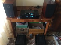
As promised a while ago here’s a short video(and a photo) of my temporary setup shaking my cage at half a watt…
https://34.filelu.com/d/rj3lj7dkjqq...gezvmivsz7ficbxh5fhjfb4vr4dlwmlm/IMG_2415.MOV
A big thanks again!
https://34.filelu.com/d/rj3lj7dkjqq...gezvmivsz7ficbxh5fhjfb4vr4dlwmlm/IMG_2415.MOV
A big thanks again!

the diyaudio site load very difficult on my side and most probably the photo didn’t upload because of that.
Edit: for the gain I need the Iron Pre is more than enough and it remained inside the preamp.
Edit: for the gain I need the Iron Pre is more than enough and it remained inside the preamp.
Attachments
today is slow ...the diyaudio site load very difficult on my side and most probably the photo didn’t upload because of that.
Edit: for the gain I need the Iron Pre is more than enough and it remained inside the preamp.
Hi schultzsch,
your movie is very impressive 👏 and your equipment looks and sounds great. Could you tell us what is the pre with the spectrum analyzer on the top or is this a diy project? 🙂
your movie is very impressive 👏 and your equipment looks and sounds great. Could you tell us what is the pre with the spectrum analyzer on the top or is this a diy project? 🙂
Merry Christmas!
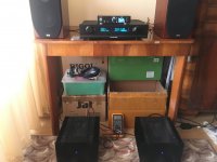
Yesterday I had the chance to put a few watts on the speakers through the boo and iron pre😎
The iron pre could give another 5db of gain but didn’t reach the maximum level with it yet(the volume was set at 0db and max is 5db).
I forgot to measure(wass too caught up with the music) but I guess there were ~5W. Even if on the fft at this levels the thd of boo is pretty high the sound is terrific.
Later I will try different mosfets on the outputs for much lower thd just to make an idea of the difference between low and high thd.
https://35.filelu.com/d/rn3clpdkjqq...q43c3zq564gmocqw6gwvtlwgdwucohel/IMG_2632.MOV
.......but I guess there were ~5W. Even if on the fft at this levels the thd of boo is pretty high .......
how's that?
as far I know it, bridged SL OS is having pretty low THD
something is fishy with your measurements
speaking of Boo itself - roughly, you can expect double or even triple of what you get in sims, depending of models used
which is still damn low
just checked - for 8Vpp, I'm getting 3 zeros after, with Cordel mosfet models
edit- that was with 1A8 Iq pper phase (sum 3A6 for channel)
checked with 1A Iq per phase, 2A channel - it's 0.001
if you're having sum Iq of 1A, well ...... build some other amp in that case 🙂
sim for 0A5 per phase, sum 1A, THD is 0.0043
Last edited:
Did you simulated like this?On the positive phase I went with 240 and on the negative with 150.
- Home
- Amplifiers
- Pass Labs
- The marriage