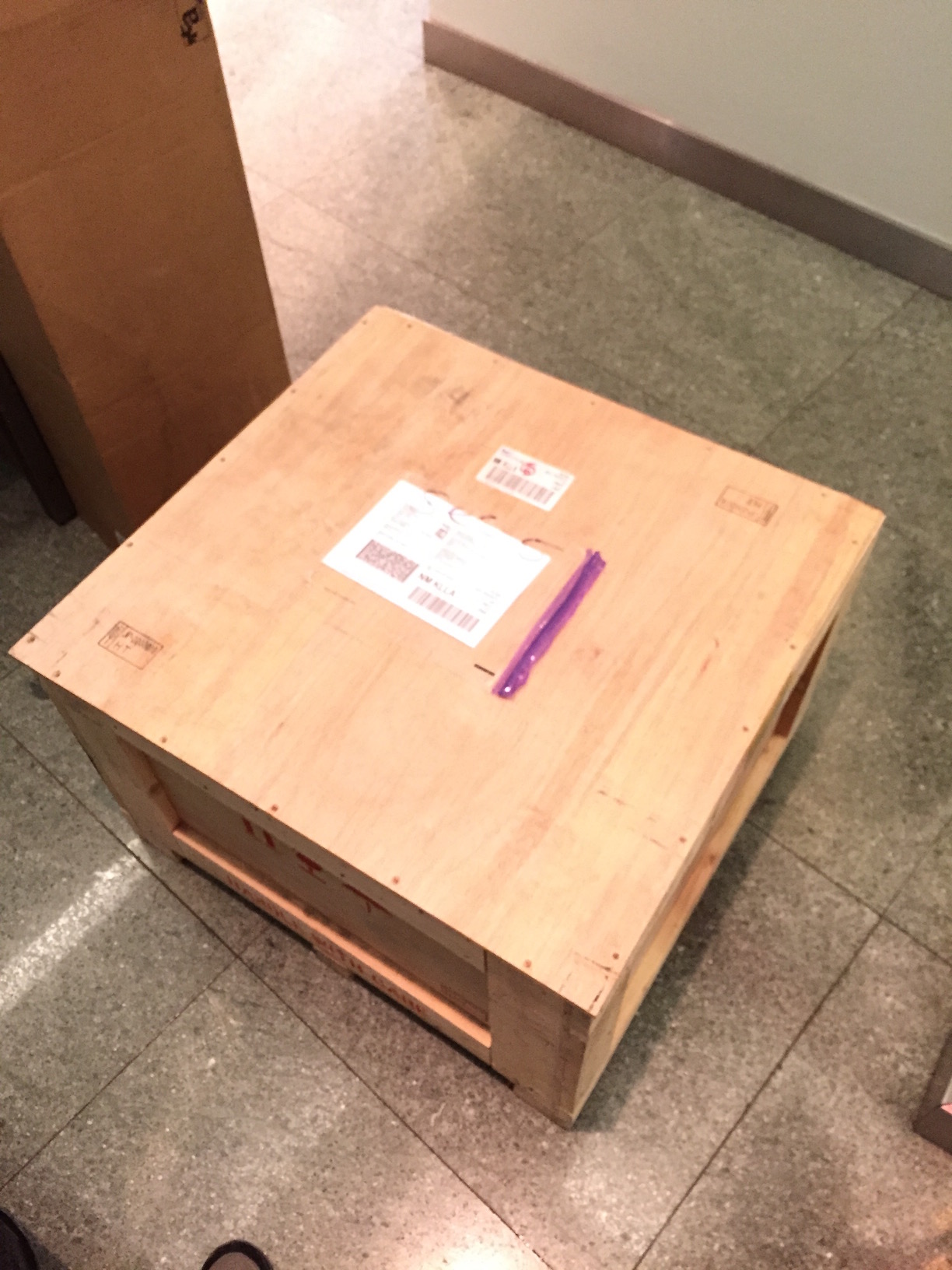
It's going to have to be tomorrow now.
It was very low but the actual flutter sidebands were largely obscured by noise. I use the Clearaudio test record and have to change it every 6 months or so.
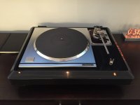
For testing I use an AT-120e cartridge which gives sufficient to feed the instrumentation directly without further amplification or EQ.
Dave
It was very low but the actual flutter sidebands were largely obscured by noise. I use the Clearaudio test record and have to change it every 6 months or so.
For testing I use an AT-120e cartridge which gives sufficient to feed the instrumentation directly without further amplification or EQ.
Dave
I'll get the Clearaudio and move some things around. I recorded in-situ, so the environment is electrically noisy. When I get the new plinth (if it doesn't arrive broken) I'll pull everything out to reduce interference.
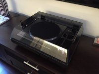
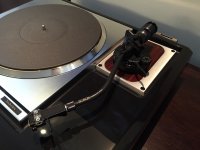
This was done with the A505 arm and an EPC-205CMK3 through an Aleph Ono to a Tascam DA-3000.
This was done with the A505 arm and an EPC-205CMK3 through an Aleph Ono to a Tascam DA-3000.
Last edited:
I'm not sure a test record is the best source of signal, as it will have the wow/flutter and what-else of the cutting lathe. At these levels, the test record's residual may exceed the turntable's. It would be interesting to attach a rotary pulse generator (optical codewheel) to the spindle and measure directly. I'm sure someone has done it already. One could also devise a way to use the platter's built-in strobe disk.
the test record's residual may exceed the turntable's.
Not yet, but your idea is interesting.
Dave
Finally!
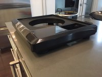
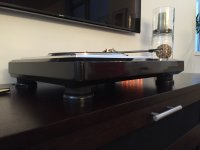
The SH-10B5 isn't made of obsidian composite like the SH-10B3 is - it's TNRC (Technics Non-Resonant Compound). The same stuff the sub-plinth in a 1200MK2 is made of, and many others. The finish isn't as smooth as the B3, but it's a brute at 41 pounds.

The SH-10B5 isn't made of obsidian composite like the SH-10B3 is - it's TNRC (Technics Non-Resonant Compound). The same stuff the sub-plinth in a 1200MK2 is made of, and many others. The finish isn't as smooth as the B3, but it's a brute at 41 pounds.
Attachments

Wow!!!!
That's impressive. I wonder what it is, as it's so dense? Something else in the resin perhaps?
That's impressive. I wonder what it is, as it's so dense? Something else in the resin perhaps?
Hi,
to me that plinth design is a timeless beauty and belongs to my personal top5 favourites.
jauu
Calvin
to me that plinth design is a timeless beauty and belongs to my personal top5 favourites.
jauu
Calvin
Thanks, all! I agree Calvin, it's a superb looking design.
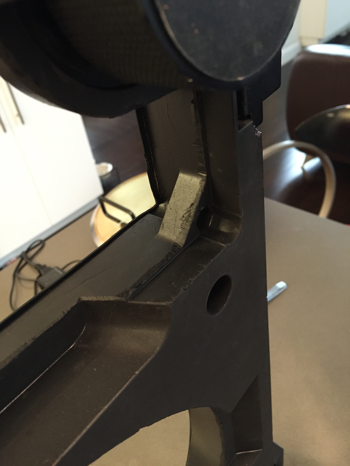
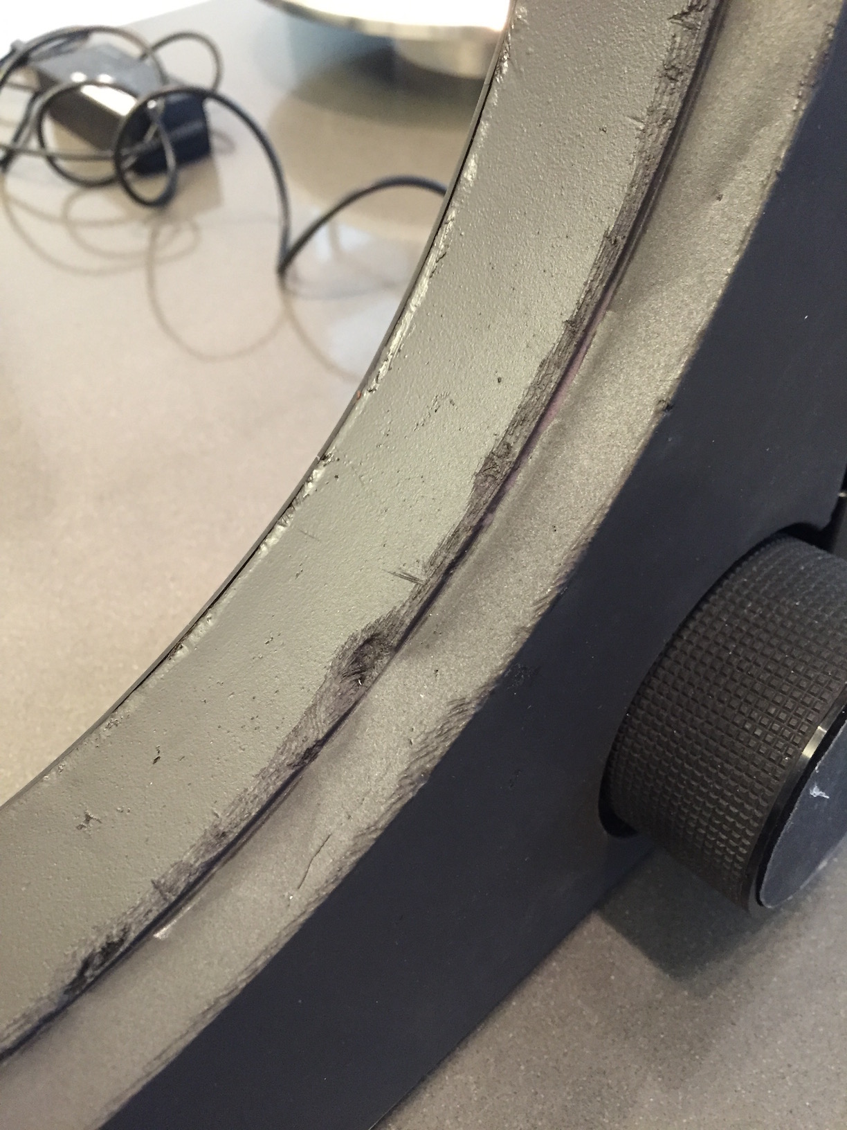
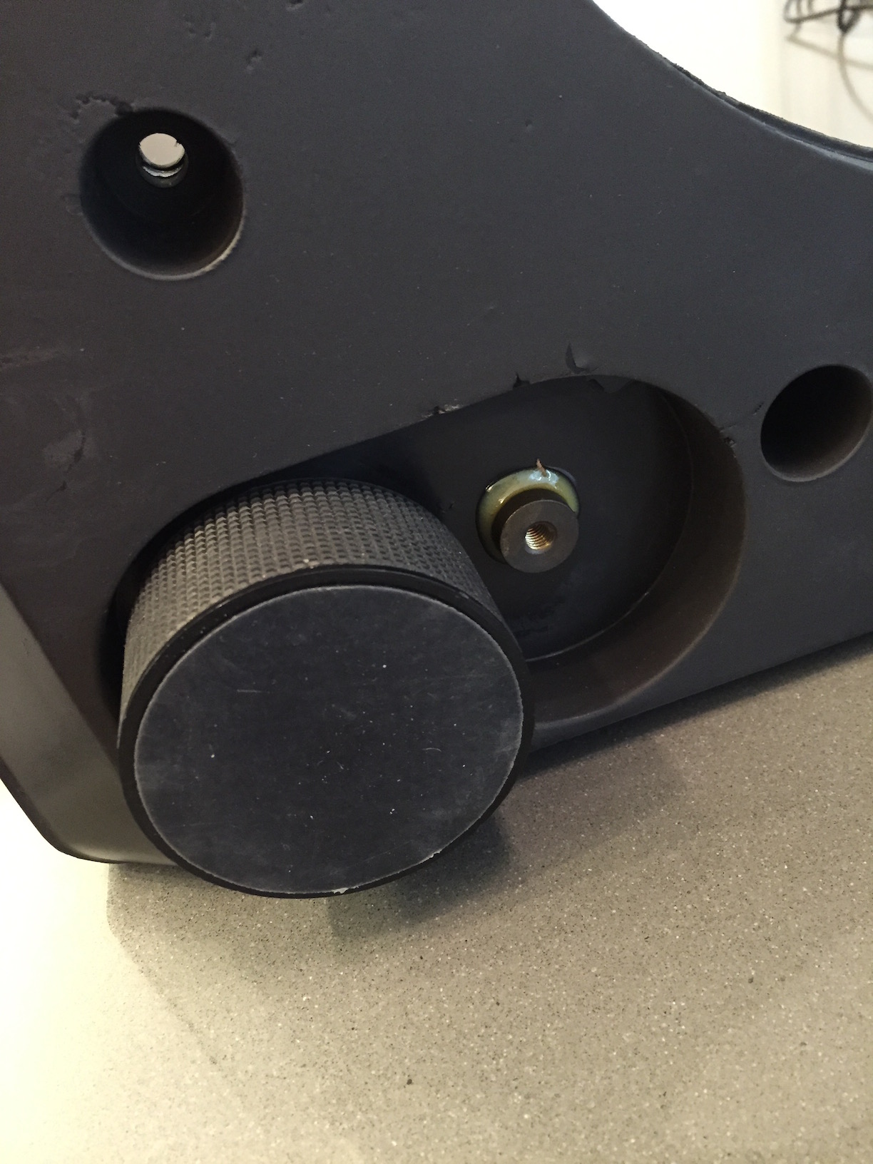
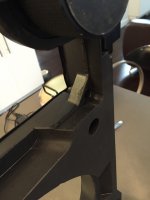
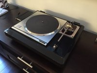
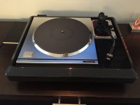
It just had to be done - I put it in full SL-1000 'regalia' today, or as close as I can get it. I'm short a badged headshell and black armboard, but it's close enough for me.
I'm still a bit dumbstruck that this thing is sitting in my living room. Though, I think Jim is the happiest about it - he doesn't have to listen to me trying to talk myself out of finding one anymore! 🙂
Attachments
I haven't listened to a MKII yet. By the time I got the plinth, I had the MK3 ready to go so I went straight to this. I'll get around to setting up the MKII sooner or later, but I wouldn't expect much of a real difference.

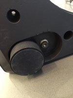
I was going through the posts on sp-10.jp and found some text that said later production units came with Q260 attached to the heatsink, and also mentioned oscillation problems when doing so which I assume is the problem I ran in to.
Well, it's a simple emitter follower voltage step down, so 100n should be fine. If I had designed it would be from base to emitter, but either way is OK.
Bourns never came through with the sample VR, but it's been running so well I'm not really motivated to replace it and have to readjust everything anyway. I went ahead and put Q260 back on flying leads today, this time with 100n across the collector and base to stabilize it. I'm pleased to report everything is running great!
Attachments
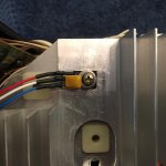
Technics SP-10 MK3 120 -240 volt conversion (110, 115, 117, 220, 230)


A few people have asked me about the 120/240 volt conversion so here are three of photos of it. All the wires are the same colours and it stands on a plate that uses the same fixing holes and allows more air through the controller.
Regards
Dave
A few people have asked me about the 120/240 volt conversion so here are three of photos of it. All the wires are the same colours and it stands on a plate that uses the same fixing holes and allows more air through the controller.
Regards
Dave
Last edited:
I noticed the output of the 'reference frequency' from the MN6042 is moving around ~15Hz for most pitch settings, including 0.0, and nearly 30Hz for some of the settings. That's a lot of movement in the clock.
The output of the DN860 is rock-steady in the eyes of the hardware counter in my scope (1Hz precision) so it would seem the issue is the MN6042. These are very early CMOS and prone to failure, and as it would appear they can also suffer from degradation.
While I have a couple spares, I'd bet there's more than a fair chance they've some degradation as well, and I really don't want to swap a bunch of 28 pin dips through my control unit. I've decided the only logical thing to do here is to make a replacement.

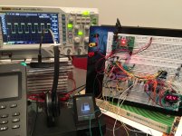
Excuse the mess - I don't have a bench since we moved to NYC, and it was easier to do this at my desk due to the programming work.
I had the board from a junk SL-1500 MK2 I picked up to strip the ICs, so I pulled the components to setup the supporting environment on the bread board. Nothing too difficult here - a PIC16 to drive the display and buttons, and a DDS to generate the clock.
I've decided to abandon the clock generated by the DN860, as using it would add components and complexity with no benefit. I don't think we'll do any worse using a DDS to generate a new clock, and it simplifies everything quite a bit. The MK3 would still use the DN860 clock to drive the strobe, though this should be fine as you'd need rather significant drift between the two clocks to be able to visually see an issue. This, of course, won't affect the bits that actually matter.
The code is done and everything is running I'd expect on the bread board. Next is to clean up the circuit a bit, and do the board design.
Soldering may prove to be the most difficult part of this project. This will certainly put my SMD skills to the test.

The output of the DN860 is rock-steady in the eyes of the hardware counter in my scope (1Hz precision) so it would seem the issue is the MN6042. These are very early CMOS and prone to failure, and as it would appear they can also suffer from degradation.
While I have a couple spares, I'd bet there's more than a fair chance they've some degradation as well, and I really don't want to swap a bunch of 28 pin dips through my control unit. I've decided the only logical thing to do here is to make a replacement.
Excuse the mess - I don't have a bench since we moved to NYC, and it was easier to do this at my desk due to the programming work.
I had the board from a junk SL-1500 MK2 I picked up to strip the ICs, so I pulled the components to setup the supporting environment on the bread board. Nothing too difficult here - a PIC16 to drive the display and buttons, and a DDS to generate the clock.
I've decided to abandon the clock generated by the DN860, as using it would add components and complexity with no benefit. I don't think we'll do any worse using a DDS to generate a new clock, and it simplifies everything quite a bit. The MK3 would still use the DN860 clock to drive the strobe, though this should be fine as you'd need rather significant drift between the two clocks to be able to visually see an issue. This, of course, won't affect the bits that actually matter.
The code is done and everything is running I'd expect on the bread board. Next is to clean up the circuit a bit, and do the board design.
Soldering may prove to be the most difficult part of this project. This will certainly put my SMD skills to the test.
Attachments
Last edited:
- Home
- Source & Line
- Analogue Source
- The Incredible Technics SP-10 MK3 Thread