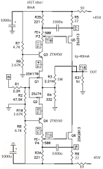
It would be very interesting how it works with the pair of matched 2SK3497/2SJ618 regarding its tempco.
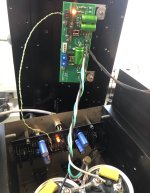
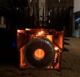
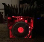
Maybe more at home in the "Pictures of your... " sticky thread but here's how things are looking these days with my ZD25 Mini.. Had a couple of small hiccups with the XA25 style discrete FE that I quickly worked through. Having a small separate power supply for these front end boards made that process quicker and a bit less painful. Initial impression is promising but will need extended listening time to decide if it stays put. Threw a couple of glamour shots in here for fun. I've been doing this "orange=left", "red=right" thing for awhile.. no particular reason, just me being me I suppose. Looks a little more vibrant in real life compared to these pictures taken with my old iPhone.
Attachments

William, your build looks amazing and very cool.
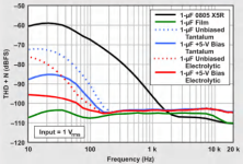
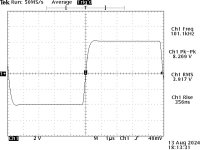
I think there are many of us being curious how the amp passes a 10 kHz square wave test loaded with 8R || 0.1uF at 1W.
After all, it is a completely different VAS that could be a game changer comparing with the OPA551 😉
I think there are many of us being curious how the amp passes a 10 kHz square wave test loaded with 8R || 0.1uF at 1W.
After all, it is a completely different VAS that could be a game changer comparing with the OPA551 😉
Well... I couldn't resist. It may be a while until I can fully finish it up, but I've started using a few spare minutes here and there to build up the second set of boards. They will ultimately wind up as a part of a 2x balanced monoblock set-up. Something about this amp makes me want to continue to push it. The standard build had 99% of the grunt needed .... but... why not?!
Also, one benefit of building in unforeseen free time vs. planning time for the build...
Why aren't the pots and op-amps in place? Well... either my spare parts inventory is incorrect, and/or I misplaced some parts... probably the latter, since I ordered plenty of both in a previous order.
Also, one benefit of building in unforeseen free time vs. planning time for the build...
Why aren't the pots and op-amps in place? Well... either my spare parts inventory is incorrect, and/or I misplaced some parts... probably the latter, since I ordered plenty of both in a previous order.
Attachments
ACnotDC - Thanks. I have to admit I did not take any measurements other than just to verify the expected gain, VAS current, IPS current, input JFET Vds, and output DC offset. Without any surprises I went ahead and installed / finalized, being anxious to hear the result. 10kHz square waves (electronic dance music) have been double blind tested only (both eyes closed, dark room, sometimes wearing only shorts, possibly accompanied by some minor head bobbing...)
William, I think that your 10 kHz double blind test with electronic dance music is more important than any scope measurement, because our ears never lie.
For me, an extensive listening session is also crucial, because what looks good on the scope does not always mean a good listening experience.
I like head bobbing too...

For me, an extensive listening session is also crucial, because what looks good on the scope does not always mean a good listening experience.
I like head bobbing too...
I was going to mention that I believe measurements absolutely have their place, I don't discount that part at all. For example if something just doesn't sound quite right,... say an unnatural treble, or things kinda fall apart when the music gets complex... you've probably gotten too sloppy somewhere in the chain. Some undesireable behaviour has crept in and now showing it's ugly head.... your distortion program, or maybe your square waves(?), or a multitude of other things that could be looked at.. are bound to tell you "see, told you so... dummy". That said, chasing the dot million zero's distortion level or perfect square waves hasn't always made me happy forever or had the effect I thought it would.
I think with an open mind you can learn and take some value from every aspect of this hobby. I like papa's approach to this stuff, measure AND listen. His favorite amplifier? "Always the next one!"...And one of my favorite's.. "It's entertainment folks"..
I think with an open mind you can learn and take some value from every aspect of this hobby. I like papa's approach to this stuff, measure AND listen. His favorite amplifier? "Always the next one!"...And one of my favorite's.. "It's entertainment folks"..

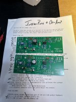
I took some time today to put a schematic together for the front end I'm showing there at post #682. Sorry for the slight crude-ness, I'm much more of a soldering citizen than a CAD jockey.. I'm pretty sure it's correct, except I didn't show the LED indicator (top secret..). As I mentioned earlier, I am powering these front ends with a separate outboard power supply comprised of a pair of Balanced Zen Line Stage PS boards (+/-45V). Power transformer(s) are Antek AN-0222's.
Sound is quite good but we'll put some more miles on this stuff..
Sound is quite good but we'll put some more miles on this stuff..
Attachments
You could tune it more with some cascode feedback.Sound is quite good but we'll put some more miles on this stuff..
Do you plan to use film caps for the 3300uf ones?
Maybe so, but just keeping it simple here. 3300uf film cap? That sounds rather massive. All the electrolytics here are just Nichicon UKA's. The DC voltage on the 3300's is very low, and not really ideal. But the circuit sounds really nice regardless and I'm not losing sleep over it.
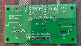
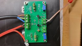
There was funny entertainment with SMD but practice makes perfect, and went without any problems.
Afterwards some dialysis on the workbench to check whether it is worth installing the front end in the HGF.
The gain was set to 20 dB at +/- 24V supply from two SMPS. Bias and the results agree well with the sim.
How it sounds? I don't know yet...
Afterwards some dialysis on the workbench to check whether it is worth installing the front end in the HGF.
The gain was set to 20 dB at +/- 24V supply from two SMPS. Bias and the results agree well with the sim.
How it sounds? I don't know yet...
Attachments
Throwing a few questions out to the hive... I know I should be able to come up with an answer, but I'm agonizing over things that likely won't matter, and perhaps missing some things that might make a difference.
The original idea was (and may still remain) to do a pair of balanced monoblocks. That's for three reasons: heatsink dissipation (temp), weight, and potential sound quality. Those are in my perceived order of importance. Perhaps... I can do it all the existing 5U/400. That would be ideal. I only need to lift it once... or twice... and similar amps have been managed. I think I can manage the heat. The SQ differences between true monoblocks and a proper dual mono have been non-existent to me.
As far as heat - I don't need the voltage swing, nor am I looking for max power into 8R. So, I'll likely stick with the existing 24V PSU, but run dual mono. I don't think buying a larger toroid is the best answer, and I can fit the extra cap boards / rectification etc. I've done it before in a 5U/400. I am a tad worried re: ~100 to 120W of dissipation per side. Based on my data (and Modushop's), I can BARELY squeak by. The proof is in the pudding. Reducing the bias current to 1A1 or 1A is an option also as needed. I'm running my stereo pair at pretty much the highest recommended, but based on previous postings, the distortion / sonics should not change in a meaningful (to me) way, by lowering the bias.
So, now comes the layout. Basically, I was thinking of two options...
1 - Mounting the toroids side-by-side at the front of the chassis. I think they'll fit horizontally. If not, I know they'll fit mounted vertically. Leave the existing mezzanine roughly where it is. Add another cap board etc. in-line with the existing mezzanine toward the back of the chassis for the other channel. Pros - both toroids up front furthest away from output / input jacks and wiring. Cons... may not fit.
2 - Essentially duplicating exactly what I have for the existing channel but toward the middle / back of the chassis. Pros - Easy and clean. Cons - Second toroid is closer to input / output jacks, but it's in a monster can. So... I'm not terribly worried.
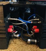
Pic of existing layout copied below.

Anything I'm missing / not considering? Ideas?
Going to get the other set of boards tested up and ready to install. 🙂
The original idea was (and may still remain) to do a pair of balanced monoblocks. That's for three reasons: heatsink dissipation (temp), weight, and potential sound quality. Those are in my perceived order of importance. Perhaps... I can do it all the existing 5U/400. That would be ideal. I only need to lift it once... or twice... and similar amps have been managed. I think I can manage the heat. The SQ differences between true monoblocks and a proper dual mono have been non-existent to me.
As far as heat - I don't need the voltage swing, nor am I looking for max power into 8R. So, I'll likely stick with the existing 24V PSU, but run dual mono. I don't think buying a larger toroid is the best answer, and I can fit the extra cap boards / rectification etc. I've done it before in a 5U/400. I am a tad worried re: ~100 to 120W of dissipation per side. Based on my data (and Modushop's), I can BARELY squeak by. The proof is in the pudding. Reducing the bias current to 1A1 or 1A is an option also as needed. I'm running my stereo pair at pretty much the highest recommended, but based on previous postings, the distortion / sonics should not change in a meaningful (to me) way, by lowering the bias.
So, now comes the layout. Basically, I was thinking of two options...
1 - Mounting the toroids side-by-side at the front of the chassis. I think they'll fit horizontally. If not, I know they'll fit mounted vertically. Leave the existing mezzanine roughly where it is. Add another cap board etc. in-line with the existing mezzanine toward the back of the chassis for the other channel. Pros - both toroids up front furthest away from output / input jacks and wiring. Cons... may not fit.
2 - Essentially duplicating exactly what I have for the existing channel but toward the middle / back of the chassis. Pros - Easy and clean. Cons - Second toroid is closer to input / output jacks, but it's in a monster can. So... I'm not terribly worried.
Pic of existing layout copied below.
Anything I'm missing / not considering? Ideas?
Going to get the other set of boards tested up and ready to install. 🙂
- Home
- Amplifiers
- Pass Labs
- The Holy Grail Follower Output Stage