Errata: Post #804 - fix inconsistencies between Build Guide schematic and PCB layout.
_______________________________________________________________________________________
The Holy Grail (HG) Follower is a complementary push-pull FET output stage with no source degeneration resistors, thereby maximizing the square-law potential of the MOSFET devices. The primary challenge with such an output stage is control its of bias current.
The "F4 Beast Builders" DIYAudio thread https://www.diyaudio.com/community/threads/f4-beast-builders.300233/post-4907053 in 2018 had many discussions of potential optocoupler circuits for bias control. The Pass Labs XA25 actually implements such a circuit. To my knowledge, none of these approaches avoided problems with the bias currents either increasing when the output power level increased.
The basic idea of the circuits is to integrate (via. a capacitor) the voltage across the drain sense resistors of the FETs. Optocouplers are used to totally isolate the inputs (LEDs) from the outputs (phototransistors). How should one combine the outputs from the NFET and the PFET? The first image below shows series, and parallel connection phototransistor outputs.

The problem with these circuits is that the bias current is not stable as the output power level is increased. The series connection results in a large increase bias current. The parallel connection results in large decrease in bias current.
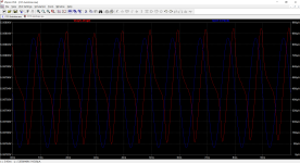
What I discovered today (Dec 20 2023) was a circuit variation that allows the continuous choice of constant, rising, or falling bias current with power level, requiring only 3 additional resistors. The second image below show the circuit and the output for a 16 Watt, 20Hz sine wave into a 6 Ohm load for each of the bias circuit topologies. The plots in the third image shows the current waveforms into the NFET after 4.8 seconds have elapsed. The plots in the fourth image show the difference in the FET gate voltages for the entire 5 seconds of the output. Green=series, Blue=parallel, Red=mixed topology.


By adjusting the 3 added resistors, the red curve can be an arbitrary mix of the green and blue curves.
What could be better for FET follower output stage with no source resistor degeneration?
_______________________________________________________________________________________
The Holy Grail (HG) Follower is a complementary push-pull FET output stage with no source degeneration resistors, thereby maximizing the square-law potential of the MOSFET devices. The primary challenge with such an output stage is control its of bias current.
The "F4 Beast Builders" DIYAudio thread https://www.diyaudio.com/community/threads/f4-beast-builders.300233/post-4907053 in 2018 had many discussions of potential optocoupler circuits for bias control. The Pass Labs XA25 actually implements such a circuit. To my knowledge, none of these approaches avoided problems with the bias currents either increasing when the output power level increased.
The basic idea of the circuits is to integrate (via. a capacitor) the voltage across the drain sense resistors of the FETs. Optocouplers are used to totally isolate the inputs (LEDs) from the outputs (phototransistors). How should one combine the outputs from the NFET and the PFET? The first image below shows series, and parallel connection phototransistor outputs.
The problem with these circuits is that the bias current is not stable as the output power level is increased. The series connection results in a large increase bias current. The parallel connection results in large decrease in bias current.
What I discovered today (Dec 20 2023) was a circuit variation that allows the continuous choice of constant, rising, or falling bias current with power level, requiring only 3 additional resistors. The second image below show the circuit and the output for a 16 Watt, 20Hz sine wave into a 6 Ohm load for each of the bias circuit topologies. The plots in the third image shows the current waveforms into the NFET after 4.8 seconds have elapsed. The plots in the fourth image show the difference in the FET gate voltages for the entire 5 seconds of the output. Green=series, Blue=parallel, Red=mixed topology.
By adjusting the 3 added resistors, the red curve can be an arbitrary mix of the green and blue curves.
What could be better for FET follower output stage with no source resistor degeneration?
Last edited:

How to include the Class AB feature of the M2OPS (with the LM385s) with this ?
https://www.diyaudio.com/community/...in-class-a-b-and-maybe-a-power-whammy.390636/
Thinking out loud,
Patrick
https://www.diyaudio.com/community/...in-class-a-b-and-maybe-a-power-whammy.390636/
Thinking out loud,
Patrick
That's very imaginative and interesting. My own (dumb) approach was to put a resistor across the bias capacitor...
You are right though, not much is better than fet followers with no degeneration.

You are right though, not much is better than fet followers with no degeneration.
Being closer to pure square law FET behavior the output stage remains in class-A at higher power levels, particularly at lower load impedances where the rail voltages are not the limiting factor.
More to come ...
More to come ...
Yes.Are the resistor values shown in the schematic appropriate for constant bias-current operation?
Ian Hegglun, whom I have a lot of respect for, has a long thread dedicated to the topics :
https://www.diyaudio.com/community/...uto-bias-power-amp.375141/page-6#post-6956053
The optocoupler bias control is one means, but not the only one.
And there were also some interesting discussions here :
https://www.diyaudio.com/community/...r-complementary-followers.317078/post-5300966
Patrick
https://www.diyaudio.com/community/...uto-bias-power-amp.375141/page-6#post-6956053
The optocoupler bias control is one means, but not the only one.
And there were also some interesting discussions here :
https://www.diyaudio.com/community/...r-complementary-followers.317078/post-5300966
Patrick
Last edited:
Thanks Patrick. Yes, there are other approached to bias control. Here are some of the goals of such a circuit:
Many other approaches that I have seen fail at goal 3.
- Stable bias over a range of heatsink temperatures, particularly during warm-up.
- Stable bias with a wide range of signal levels.
- Practical to implement without limited choice of devices and tight matching of their parameters.
Many other approaches that I have seen fail at goal 3.
Have you considered sensing the current at the power supply instead ?
We are only interested in long-term drift of DC current, right ?
Patrick
We are only interested in long-term drift of DC current, right ?
Patrick
Power supply, if large enough output cap, will see much less of the signal, depending on where you sense.
Of course can always add LP filter on top.
Patrick
Of course can always add LP filter on top.
Patrick
Member
Joined 2009
Paid Member
Further iterations available for fine tuning of bias down besides the power rail resistors also...
You tested this ?
You are running at 2.5A bias ?
How much do your current sources drift with temperature ?
Patrick
You are running at 2.5A bias ?
How much do your current sources drift with temperature ?
Patrick
Yes, 2.5 amps on a big hs. Little drift after warm up, not too much. Higher value resistors or a precision current source btw bases of pnp/npn bjt's as Zen Mod did before in one of his designs, or just a pot. Few mAmps after warm up not much.
As in the post no 6 of Zen Mod's
https://www.diyaudio.com/community/threads/sissysit-r-3.371272/
a precision ccs will allow fine tuning the bias down...
Extremely stable after few mili amps drift/settle after warm up.
As in the post no 6 of Zen Mod's
https://www.diyaudio.com/community/threads/sissysit-r-3.371272/
a precision ccs will allow fine tuning the bias down...
Extremely stable after few mili amps drift/settle after warm up.
Last edited:
According to spice, post #16 works quite well in DC.
But when a large signal of +/-20V 1kHz is applied, one can see that the sum of the two gate voltages is not quite constant.
And distortion is also not small, even at lower amplitudes.
I think I need some more investigation.
But thanks for sharing.
Patrick
.
But when a large signal of +/-20V 1kHz is applied, one can see that the sum of the two gate voltages is not quite constant.
And distortion is also not small, even at lower amplitudes.
I think I need some more investigation.
But thanks for sharing.
Patrick
.
Attachments
- Home
- Amplifiers
- Pass Labs
- The Holy Grail Follower Output Stage