That's a very interesting approach. Congratulations
Maybe that would be something for me too.
I'm looking for a HGF variant that offers a good DF, because my speakers have very erratic impedance curve.
At the moment I've ended up with DF = 350 with my front end and a global feedback of just 6 dB. But there is trouble with a little ringing that occurs with a complex load of 8R || 100 nF

The ringing might not be the fault of the amplifier. If the square-wave has very fast rise/fall times then it is important the scope probe and it's ground are close to output FETs and the ground point on the PCB. Otherwise, the trace/wire inductance will introduce ringing.
Thank you very much for the tip, Lynn 
There are always things that are not taken into account or simply forgotten.
I also ignored the old German saying "he who measures a lot, measures a lot of crap" (wer viel misst, misst viel Mist)

There are always things that are not taken into account or simply forgotten.
I also ignored the old German saying "he who measures a lot, measures a lot of crap" (wer viel misst, misst viel Mist)

Our experience with apparent ringing.
https://www.diyaudio.com/community/...tage-perfectly-integrated.406024/post-7594493
Followed by post #112 & #131.
Patrick
https://www.diyaudio.com/community/...tage-perfectly-integrated.406024/post-7594493
Followed by post #112 & #131.
Patrick
Don’t worry about a thing (Bob Marley). 🙂But there is trouble with a little ringing that occurs with a complex load of 8R || 100 nF
Fast amplifier must ring with capacitive load. It’s not a sign of problem. Here is an example with explanation:
https://www.diyaudio.com/community/...y-simulated-vs-real-world.407089/post-7548890
I took some time this morning to attempt measurements. Complete SNAFU.
Quick summary... DODO move on my part. Used the wrong measurement jig / technique.
Longer version - I have my own measurement "jigs" for my QA. I used the wrong wiring harness. I used the 'non-bridged' / 'standard' harness. So... after the experienced readers have cleaned their screens, I'll explain what I've done and potential consequences, so that those less experienced may not suffer the same gut punch. I've read similar before, and it doesn't necessarily need repeating, but if it saves even one person from smoking an amp or even some inconvenience, it'll be worth it.
For standard (non-bridged) amplifiers one side of the speaker / load is at ground potential as reference / return and the other is generally considered the "output".
So, a simple diagram may be something like this.

For balanced / bridged amplifiers, both outputs 'float' and are at equal and opposite potential with no ground reference / return. A diagram may look something like this.

All graphics shamelessly borrowed from the link below... which conveniently is also in my own QA measurement procedure notes... which I did not review b/c I am a total dodo, and thought "I know what I'm doing".
https://melp242.blogspot.com/2019/05/measuring-bridged-and-balanced.html
What I have yet to understand is why using my standard harness caused what I can only assume is oscillation. When I turned on the signal, I immediately smelled something "hot" and I could actually hear a ringing / tone. Fortunately I shut the amp down immediately.
I'll further assess any damage tomorrow. For the moment... I shouldn't be allowed anywhere near electronics. I hope all that's damaged is my ego.
Quick summary... DODO move on my part. Used the wrong measurement jig / technique.
Longer version - I have my own measurement "jigs" for my QA. I used the wrong wiring harness. I used the 'non-bridged' / 'standard' harness. So... after the experienced readers have cleaned their screens, I'll explain what I've done and potential consequences, so that those less experienced may not suffer the same gut punch. I've read similar before, and it doesn't necessarily need repeating, but if it saves even one person from smoking an amp or even some inconvenience, it'll be worth it.
For standard (non-bridged) amplifiers one side of the speaker / load is at ground potential as reference / return and the other is generally considered the "output".
So, a simple diagram may be something like this.
For balanced / bridged amplifiers, both outputs 'float' and are at equal and opposite potential with no ground reference / return. A diagram may look something like this.
All graphics shamelessly borrowed from the link below... which conveniently is also in my own QA measurement procedure notes... which I did not review b/c I am a total dodo, and thought "I know what I'm doing".
https://melp242.blogspot.com/2019/05/measuring-bridged-and-balanced.html
What I have yet to understand is why using my standard harness caused what I can only assume is oscillation. When I turned on the signal, I immediately smelled something "hot" and I could actually hear a ringing / tone. Fortunately I shut the amp down immediately.
I'll further assess any damage tomorrow. For the moment... I shouldn't be allowed anywhere near electronics. I hope all that's damaged is my ego.
A friend of mine pointed this thread to me and I really enjoyed reading it. I was intrigued in building this amplifier, although with some changes.
First of all, I must note that I own a pair of horn speakers, so 5 Watts of power is more than enough for me (actually, I have built a 2W tube amp that drives my speakers without any problem). Also, I happen to have in hand some Fairchild FQA19N20 and FQA12P20 MOSFETs left from a F5 project that never started.
So, I was thinking of using these MOSFETs and a lower power supply voltage (+/- 16 V), with the versatility of using standard supple voltage opamps.
Could you please comment on my above cited thoughts?
Evangelos
I have not tested that FET pairing, but looking at the datasheets I think they would work, but I am not sure I woul go as low as +/-16V of the supplies.Also, I happen to have in hand some Fairchild FQA19N20 and FQA12P20 MOSFETs left from a F5 project that never started.
Since OPA551 does not swing it output to the rails, you will get only about +/13V out the the amp with 16V rails.So, I was thinking of using these MOSFETs and a lower power supply voltage (+/- 16 V), with the versatility of using standard supple voltage opamps.
With 16V rails, the preferred option would be to use an different opamp that swings to the rails and can operate at 16V. This potentially causes stability problems requiring careful attention to bandwidth limit the front end.
What would be the limitations with lower PS voltage?I have not tested that FET pairing, but looking at the datasheets I think they would work, but I am not sure I would go as low as +/-16V of the supplies.
Yes, I was considering using OPA828 or OPA 132.With 16V rails, the preferred option would be to use an different opamp that swings to the rails and can operate at 16V.
Mainly output power.What would be the limitations with lower PS voltage?
Strange choices: Neither packaged in 8-pin DIPs or have rail-to-rail output.Yes, I was considering using OPA828 or OPA 132.
Opa1656. Or use adapter that uses only one opa from a dual one and go for opa2156, almost no offset, rail to rail both input and output. And doesn't really get bothered with +-16V.
As I mentioned, an output power of ca. 5W is more than adequate for me.Mainly output power.
I happen to have a couple of OPA132 in 8-pin DIP package back from the early 00s. Also, I could use a SOIC to DIP adapter for the OPA828.Strange choices: Neither packaged in 8-pin DIPs or have rail-to-rail output.
I wasn't aware of this opamp. I will have a look at it. Thank you!Opa1656. Or use adapter that uses only one opa from a dual one and go for opa2156, almost no offset, rail to rail both input and output. And doesn't really get bothered with +-16V.
I checked TI's info on OPA 828 and it mentions that it has a rail-to-rail output capability.Strange choices: Neither packaged in 8-pin DIPs or have rail-to-rail output.
Not possible for OPA132 though.
Well, I've either damaged something and/or something is just not quite correct with the left channel. See below.

In order to diagnose further, what I want do do is narrow it down to one or both of the boards (positive or inverted phase) within the left channel.
I've read more and more, but I got completely wound around the axle, and I wonder (again) whether I'll do further/potential damage with floating outputs and not yet completely grasping how to measure properly.
My idea is to measure each of the boards independently while still wired in their current configuration. Specifically, I was going to measure the output of each board with GND as the reference vs. differential to the other board.
The source signal would still enter per norm, and the input wiring separates the phases; + to "Board 1" and - to "Board 2".
If I measure the output of each board using the differential input of the QA, I should be fine, I think. I'd connect probes to the output test point and GND on each board vs. across the binding posts.
My silly question is ... if the load is connected across both boards, what load does each board "see"? Is there any issue with my lame-brained idea to narrow this down?
Crude diagram below. I'd do the output for both boards separately. Below shows output from + phase board to input of the QA.

After two measurements (+ board and - board separately); I should have the amplified output of the positive and inverted waveforms referenced to GND, correct?
Edited to show proper connection to from the QA input to the amp board GND (jumper wire) in the crude diagram.
In order to diagnose further, what I want do do is narrow it down to one or both of the boards (positive or inverted phase) within the left channel.
I've read more and more, but I got completely wound around the axle, and I wonder (again) whether I'll do further/potential damage with floating outputs and not yet completely grasping how to measure properly.
My idea is to measure each of the boards independently while still wired in their current configuration. Specifically, I was going to measure the output of each board with GND as the reference vs. differential to the other board.
The source signal would still enter per norm, and the input wiring separates the phases; + to "Board 1" and - to "Board 2".
If I measure the output of each board using the differential input of the QA, I should be fine, I think. I'd connect probes to the output test point and GND on each board vs. across the binding posts.
My silly question is ... if the load is connected across both boards, what load does each board "see"? Is there any issue with my lame-brained idea to narrow this down?
Crude diagram below. I'd do the output for both boards separately. Below shows output from + phase board to input of the QA.
After two measurements (+ board and - board separately); I should have the amplified output of the positive and inverted waveforms referenced to GND, correct?
Edited to show proper connection to from the QA input to the amp board GND (jumper wire) in the crude diagram.
Last edited:
For those playing the home game... I don't mind sharing when I don't know something / or when I goof up. Maybe someone will learn from my error.
A kind-hearted soul pointed out my error above - the measured signal from the single amp board should be directly connected to the GND at the QA vs. measured as a differential to GND. I still am not completely 100% clear re: why, but I think I'm 90% there. Simple wiring change to get the measurements done properly for troubleshooting each board. They also explained why one specific board may have oscillated when I used the incorrect wiring for measuring the output. I am 99% sure I understood that.
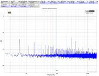
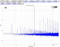
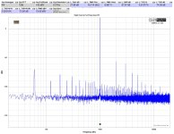
Either way (ignoring all the mains grass / noise) - It should be pretty clear which board was heating up a tad / created the "warm" smell from the FFTs below. Without measurement gear... would I have noticed? Who knows?
I'll pop that board out and go over it. The kind soul said to first possibly just replace the op-amp. However, if anyone has any other ways to determine what other parts may have been damaged, I'd be thrilled to know. There's no visible damage to any parts.
With the exception of the output devices, I have all the parts in-house... and... since I have been known to make an error or two occasionally, I'm quite adept at part replacement.
Cheers! What an incredible community.
Attachments
I would check the bias current of the power Mosftes first. OPA551 is internally protected against temperature and current overload but not against overvoltage.
Looking at your performance measurements of THD another question comes to my mind.
If you compare your measurement results from the balanced and the original configuration with a linear PSU (post #400), you'll notice that in the power range up to 1 W there are no improved THD values. The most performance advantage seems to be in the high power range from 1 W upwards.
Why is that the case, even though the even harmonics cancelation?
- Home
- Amplifiers
- Pass Labs
- The Holy Grail Follower Output Stage


