I have built several amps using the ModuShop heatsinks and believe that the 1.4 "fudge factor" is about right.
I have also used the natural convection heatsink simulator called Natsink which does a good job predicting the thermal resistance of the heatsink. This was a Windows program from 10 years ago (or longer) that I can still runs but I cannot locate it online.
I have also used the natural convection heatsink simulator called Natsink which does a good job predicting the thermal resistance of the heatsink. This was a Windows program from 10 years ago (or longer) that I can still runs but I cannot locate it online.
@lhquam thank you. I have the modushop 5U 200, rated at 0.28°C/W (times 1.4 it seems, I don’t understand the explanation of 85°C …)
@poseidonsvoice thank you too 🙂
I‘m just in the process of toning down the bias to 1A (110mV across R1) which is a breeze to achieve, this amp is so calmly stable, although offset is a bit jumpyer, but i got it tamed in the sub-mV…
Babysitter’s parts are under observation (not yet ordered), as summer is coming closer every day. (I‘m not keen to go under the engine hood to bring the V down)
…
Gianluca posted and gave me permission ages ago to repost the study upon which their dissipation ratings are based. I can't find where he or I originally posted it to link, so I've attached it.
I extrapolated some of the data from the charts to make my own calculations/predictions for heat rise above ambient for various Modushop '40mm' heatsinks that were not part of the original study for the chassis included in the paper. They're pretty accurate. Rules of thumb provided by various members haven't led me astray either.
YMMV, but the main thing is that no heatsink manufacturer (that I've found) publishes their de-rated tc at various temperatures, so we usually fudge.
Note - this study was done with chassis vs. bare heatsinks. I don't know how they calculated Tc for other various heatsinks. I'm sure if I asked, he'd provide further information.
Cheers,
PA
Attachments
The offset can be 50mV (or more) without any worry. If you ruin the amp without any global feedback you can expect the offset to be less stable, but that does not appear to present any problems for the speakers or the sound quality.... this amp is so calmly stable, although offset is a bit jumpyer, but i got it tamed in the sub-mV…
...
This is comforting! And no, I don’t intend to run (ruin 😉 ) the amp without gf, so I‘m double-good.
Re: heatsinks, I hope nobody misunderstood me in the situation, I truly trust gianluca, when he says something is that or this way, he says it with a reason.
Re: heatsinks, I hope nobody misunderstood me in the situation, I truly trust gianluca, when he says something is that or this way, he says it with a reason.
I found this: https://www.heatsinkcalculator.com/heat-sink-size-calculator.html
It can give you some idea of your heatsink behavior if you have various dimensions.
It can give you some idea of your heatsink behavior if you have various dimensions.
This has been a lot of information, and the HS efficiency-questions seem to have been answered 🙂
As the Mosfets seem to feel comfy in a warm housing, I'll see how it sounds biased at 1A, and may up it again to 1.25 later...
(Since many if not most of us builders seem to rely on rules of thumb (or even rule of fist), methinks these informations should be given a bit more publicity, like in a sticky thread in the parts-forum or something, as it would be really helpful to have some clearer data-points to relate to.)
Thanks ItsAllInMyHead for gifting the active rectifier PCB's, now in use in my amps. I was able to successfully extract and reuse all 20 active devices to make it happen from a pair of unused PS boards (those parts aren't cheap). Rails @~27V now, Iq is ~1.4A. Really nice amp, system just oozes detail, resolution, and clarity..
Attachments
no heatsink manufacturer (that I've found) publishes their de-rated tc at various temperatures, so we usually fudge.
Linear audio vol. 3, free download at my request.
Patrick
.
Attachments
Last edited:
Natsink will allow you to simulate finned heatsinks of various dimensions.
Usually a tiny bit conservative. I use it all the time.
https://www.diyaudio.com/community/...k-heatsink-simulation-app.410698/post-7637221
Patrick
Usually a tiny bit conservative. I use it all the time.
https://www.diyaudio.com/community/...k-heatsink-simulation-app.410698/post-7637221
Patrick
Last edited:
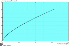
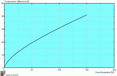
Attached are 3 simulation results from Natsink.
All of them with correct base plate thickness, trapezoidal fin dimensions, etc.
The first is the Hifi2000 sink 200x165x40mm.
You have 2x on each side, so ideally can double the power.
The second is a fictitious heatsink measuring 400x160x50mm, i.e. 10mm higher fins.
The third is what we used in the F5X, which is also similar to the Conrad heatsink MF35.
Dimensions are 350x150x50mm.
As you can see, dT/dW is not constant and is dependent on power dissipated.
Cheers,
Patrick
.
Attachments
^ Thank you for posting all the helpful additional links / files! 🙂
For the Modushop heatsinks, I used the study kindly provided by Gianluca, and I manually extracted the data (visually from the plots) and did a quick regression analysis to create a model for theirs. There were a few other chassis sizes I like that were not included in the study, so I used the same data to get a ballpark for other sizes. It was fun. I don't like to run my heatsinks at as high a temperature as many, and I have generous amounts of space, so I tend to run fairly large chassis. It also allows me to fiddle with bias currents / voltages => overall dissipation a little bit while I learn without much fear of going overboard on temps. I'm comfortable up to about 45C, but I've pushed a few to 60C for short periods of time just to see what all the fuss was about.
Now... I need to get off my rump and finally get some proper heat spreaders fabbed up for my two-piece heatsinks... I know it's the 'right' thing to do, I just haven't done it.
Thanks again for sharing your knowledge!!!
Thank you for saying this much more clearly than I did above. I have not found a manufacturer that publishes the 'curves' for their heatsinks. I have run across some of the sims you mention. The LA article is also a lovely reference. I added that to my learning library.As you can see, dT/dW is not constant and is dependent on power dissipated.
For the Modushop heatsinks, I used the study kindly provided by Gianluca, and I manually extracted the data (visually from the plots) and did a quick regression analysis to create a model for theirs. There were a few other chassis sizes I like that were not included in the study, so I used the same data to get a ballpark for other sizes. It was fun. I don't like to run my heatsinks at as high a temperature as many, and I have generous amounts of space, so I tend to run fairly large chassis. It also allows me to fiddle with bias currents / voltages => overall dissipation a little bit while I learn without much fear of going overboard on temps. I'm comfortable up to about 45C, but I've pushed a few to 60C for short periods of time just to see what all the fuss was about.
Now... I need to get off my rump and finally get some proper heat spreaders fabbed up for my two-piece heatsinks... I know it's the 'right' thing to do, I just haven't done it.
Thanks again for sharing your knowledge!!!
Heatspreader won't help.
The additional conductive (fluid) medium between spreader and sink does more harm than any good by adding the spreader.
Read the LA article.
The only solution is one-piece heatsinks.
https://www.fischerelektronik.de/we... extruded heatsinks/VA/SK479150SA/index.xhtml
Or you use highly conductive (meaning silver loaded) thermal paste in between.
Or aluminium soldering.
Patrick
Last edited:
I did read the article (three times now), but I admit I must have misinterpreted and/or made some incorrect assumptions.Read the LA article.
The article doesn't specifically mention two-piece heatsinks. It discusses pros / cons of using a heat spreader over a single-piece heatsink (if I understood correctly).
I assumed (obviously incorrectly) that the advantages of a heatspreader (if properly implemented) outweighed the negatives for two-piece heatsinks.
Either way, you have my thanks yet again for a direct answer to a specific situation vs. me trying to guess. I have plenty of leftover tubes of thermal pastes for CPUs (lots of things referring to the Arctic or bears and silver or whatever) ... I can give that a whirl and see how it performs. Potential benefit at low-to-no added cost on my end.

Hi guys. Just adding the gerbers into my JLCPCB basket. The ZD25.zip doesn't show any silkscreen but is the correct size. The JLC zip does have silkscreen but shows the extended board outline around the outputs as has been mentioned. Shall I just go ahead and order with the JLC file?
Thankyou
Thankyou
Attachments
My understanding is that JLCPCB uses the .OLN file to define the board outline.
I had some issues submitting my order from them about this when I submitted my order that was resolved after a couple of Email exchanges.
In the future I might have to make sure that the silkscreen layer does not extend past the board outline.
I had some issues submitting my order from them about this when I submitted my order that was resolved after a couple of Email exchanges.
In the future I might have to make sure that the silkscreen layer does not extend past the board outline.
I finished the amp this evening and I'm working on the bias. It went together smoothly and easily.
It plays nicely with my balanced Iron Pre. Well done, Lynn.
Thank you, to all who make this hobby possible- lhquam, IAIMH, Birdbox, Rthatcher, 6L6, Gianluca, ZM and Papa! Love you all.
It plays nicely with my balanced Iron Pre. Well done, Lynn.
Thank you, to all who make this hobby possible- lhquam, IAIMH, Birdbox, Rthatcher, 6L6, Gianluca, ZM and Papa! Love you all.
Attachments
Amp developed a little instability (kept triggering DC offset protection), took it out and started to fiddle, my input opamp was on a soic - dip adapter and the heat must have forced the adapter up out of the socket, added some good old hot glue and all is happy at the round table. I should just have soldered it in originally...
- Home
- Amplifiers
- Pass Labs
- The Holy Grail Follower Output Stage


