Heat sinks and heat spreader? The answer seems to me to be, it depends.
For instance, if there are two equal heat sinks and two devices with equal dissipation, then mount one device on each heat sink with no heat spreader. If two equal heat sinks and one device, then mount the device on a heat spreader attached to the two heat sinks. If two equal heat sinks and four devices with equal dissipation, mount two devices on each heat sink with no heat spreader., This assumes the devices are mounted in optimal locations on the heat sinks. So it depends on the numbers and combinations.
For instance, if there are two equal heat sinks and two devices with equal dissipation, then mount one device on each heat sink with no heat spreader. If two equal heat sinks and one device, then mount the device on a heat spreader attached to the two heat sinks. If two equal heat sinks and four devices with equal dissipation, mount two devices on each heat sink with no heat spreader., This assumes the devices are mounted in optimal locations on the heat sinks. So it depends on the numbers and combinations.

I recently ran some simulations of the ZD25-Mini in a balanced bridged configuration driven either from a balanced XLR input or a single-ended RCA input. With only a few minor resistor and wiring changes it appears that this bridged amplifier can produce nearlt 100W into an 8 Ohm or 4 Ohm speaker load with essentially the same idle power dissipation as the unbalanced stereo configuration.
Shown below is the wiring for the XLR and RCA input configurations.

Shown below is the wiring for the XLR and RCA input configurations.
Connecting them like this can benefit when using smps because you can lower the rail voltages and increase a bit the bias to increase the class a envelope which now is smaller.
I played with square law ops in The marriage thread and this ops(square law) has an advantage over the degenerated ones, it performs better into lower loads which makes it a good candidate for bridged stuff.
I played with square law ops in The marriage thread and this ops(square law) has an advantage over the degenerated ones, it performs better into lower loads which makes it a good candidate for bridged stuff.
I agree about the lower rail voltages and higher bias current.
One negative is the damping factor is decreased due to the two output impedances of the two phases being in series.
Another benefit is that the current loads on the rails are of opposite phase, thus the summed rail current loads are more uniform.
One negative is the damping factor is decreased due to the two output impedances of the two phases being in series.
Another benefit is that the current loads on the rails are of opposite phase, thus the summed rail current loads are more uniform.
Last edited:
I think you wanted to say decreased?damping factor is increased
There are always trades to be done...
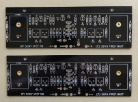
With a nudge and a wink from mighty generg when he reached out with a PM.... I've been prepping these "2017 Sony VFET" pcb's from the clearance rack at the diyAudio Store. As a continuation my comment at #615, this is another discrete FE experiment I just have to try. The XA25 FE seems like a natural fit (well something close to it), and I have the active's here to do it. The circuit will get some of my usual hack-n-slash to make it work, but shouldn't need too much of that. I removed the unneeded areas of the pcb's to enable fit, form, and function (absolutely wear a good mask and protect yourself from that dust if you ever do such a thing, nasty nasty stuff...), and used one of my bare Stasis FE boards as a template for the mounting holes and edge guide for the dremel work. I haven't done a test fit yet, but should drop right in. With the cascoded input stage and some silicon that will perform better doing a little "work" (a tired puppy is a good puppy), it's just begging for a nice separate boosted/regulated supply. I have one ready to go (±45V, BZLS PS based), just need to install the mating connector onto the back of my amps..
Attachments
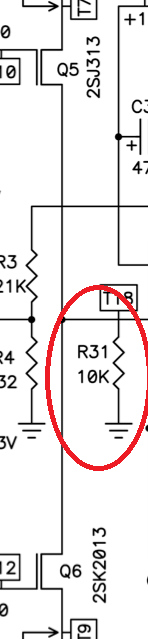
One thing I am uncertain of, is this VAS loading resistor, in regards to pairing this with the ZD25 Mini output stage. I seem to remember people using something quite a bit lower there... 1K? I'm way behind the curve like always... F4 Beast Builders thread etc. Lynn?
Attachments
The Holy Grail Follower (HGF) front end (FE) integration with the OS is a bit different from the XA25 (or ZD25).
There are aspects of the VAS loading resistor that must be considered:
There are aspects of the VAS loading resistor that must be considered:
- Lowering its resistance presents more current load to the FE, which can limit the FE voltage swing,
- Lowering its resistance will decrease the open-loop gain, and consequently also lower the amount of negative feedback.
Here is another example of a FE for HGF output stage.
It is simlpy a low-power F5m with output power MOSFETs changed to FQP3N30 and FQP3P20. The bias current and offset are set with trimmers U2 and U3, e. g. about 75 mA, but one can set it higher that may be even better if they are directly mounted on the OS heat sink.
The voltage gain is set by the quotient R3/R4 and it defines also the amount of a local current feedback. A mixed feedback can be achieved with connecting additional resistor R9 from the OS output to the junction point of R3 and R4.
The THD from sim looks good with 0.0069 at 1kHz.
What would be the pros and cons of such solution?
Special thanks to EUVL for making the sim of F5Pi project available.
Attachments
That should work, but I don't know about the mixed feedback. I need to do some sims and circuit analysis.
- Pro: Can be scaled to higher voltage swings than the opa551 if cascoding is used of the JFETs.
- Con: Many more parts than the opa551.
That’s essentially the BA3 front end. The mixed feedback scheme seems to have worked out well when pairing various front ends to the M2OS, so I wouldn’t expect too much trouble here.
A major difference from the BA3-GS is the open-loop gain. The BA3 uses no global feedback and deliberately has low gain, vs. the F5Pi topology.
The circuit in post #671 is similar to the XA.8 front end without cascoding.
The circuit in post #671 is similar to the XA.8 front end without cascoding.
What would be the pros and cons of such solution?
You need to simulate the whole circuit, with the OPS, in the frequency domain, with a reactive load, to check for phase and gain margin.
Or look at open loop frequency response.
Patrick
Yes, it is clear that only the simulation of the entire system is meaningful. THD is not everything.
So, the determined parameters look like this:
CLG = 14 dB at 1 kHz, f(-3dB) = 1.7 MHz with phase shift -52°
OLG = 48 dB at 1 kHz, f(-3dB) = 36 kHz with phase shift -88°
Even the reactive loads like Kantor don't bother it, it remains stable.
It's just the amount of negative feedback around 34 dB and the low bandwidth in open loop that makes me think.🤔
For those who are more curious, I've attached the sim.😉
Attachments

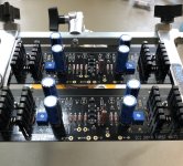
Getting closer.. Looks pretty much like everyone else's Sony VFET printed circuit assemblies from back in the day minus the amputations. The extra 'lytics there are part of the RC filtering for the power rails (10 ohm, 1,000uF / 50V), and the VAS degen bypass caps (3,300uF / 16V). Those four caps just happen to be exactly the same physical size which makes my OCD happy. I'm using 22 ohm degeneration resistors on the VAS... just going with what generg shared with me. I plan to run the VAS stage @Iq=40mA to start. CLG is a little over 16 dB. The big beefeater feedback resistor is there just to keep any PCR in check (Power Coefficient of Resistance is the change in resistance as a function of self-heating) bigger part=better thermals. The entire voltage swing of the amp will enter this node, and any distortions in the feedback network (resistor TEMPCO, VOLTCO, PCR) can't be corrected by the action of the feedback mechanism itself. I'm sure the effect is minor in any case... but there it is..Can't wait to see how it evolves.
Attachments
I was interested to determine performance limits of a balanced/bridged HGF.
Here are some measurements of the HDF (ZD25-Mini) in a balanced/bridged configuration as shown in post #662 using
the packaging shown in post #480 https://www.diyaudio.com/community/threads/the-holy-grail-follower-output-stage.406850/post-7662934.
Here are some of the parameters:

As one would expect, the second harmonics of the two phases (mostly) cancel.
These are truly amazing results.
I plan to do some experiments with different FETs, such as IRFP140/9140 in one of the channels in order to introduce some 2nd harmonic (H2). This would be similar to the way the PassLabs XA.8 amplifiers introduced H2 vs. the XA.5 amplifier series.
Here are some measurements of the HDF (ZD25-Mini) in a balanced/bridged configuration as shown in post #662 using
the packaging shown in post #480 https://www.diyaudio.com/community/threads/the-holy-grail-follower-output-stage.406850/post-7662934.
Here are some of the parameters:
- Rail Voltages: +/-29V. Max voltage for the MeanWell LRS-200N2-24 SMPS.
- Bias current: 1.18A
- Heatsink Temnperature: Stable at 27C above ambient.
- FETs: FQA28N15 / FQA36P15
- 8 Ohms Load: output is rail voltage limited to 170 Watts (+/-52V peak) with a THD of 0.01%.
- 4 Ohms load: harmonic rolloff clean until around 240 Watts (+/-43.8V peak) with THD of 0.03%.
As one would expect, the second harmonics of the two phases (mostly) cancel.
These are truly amazing results.
I plan to do some experiments with different FETs, such as IRFP140/9140 in one of the channels in order to introduce some 2nd harmonic (H2). This would be similar to the way the PassLabs XA.8 amplifiers introduced H2 vs. the XA.5 amplifier series.
- Home
- Amplifiers
- Pass Labs
- The Holy Grail Follower Output Stage