lt1166
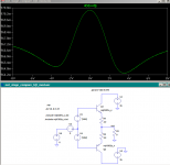
Trouble with LT1166 begings when u use pin2, transconductance stage of the chip. Behaves nastily in HF region.
Also note that compensation needs to be symmetric rather than one sided from the driver stage.
If you are not really after instrumentation level of performance (o-ish thd), then this 2$ chip can be handy.
For simulation use SYN08 model.
atiq - other decent solution for dynamic biasing amp can be found using LT1166 bias chip (without pin 2).
looks like the LT1166 is part of a typical boosted bias circuit
with the wave shaper inside (maybe), anyone have the
datasheet??
Driven by a lm4702c ( a future frugalamp)none the less..
Don't worry about offtopic , I am scraping ALL knowledge up
for this one. Op-amp designs.... obscure IC's , I'll steal any good
idea. The only issue with actually using a IC is , with my luck,
I'll build a amp I really like and they will discontinue the IC. 🙁
(I do like the 4702c a LOT)
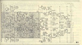
thank you ,atiq the JVC A-X9 is super a in a totally discreet
form .
Os
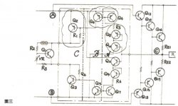
I dont think its that amp then, its a non switching AB and that sounds more like a class a amp. I found this on a chinese site though, the pick says its a audiotek from 1978, and I kinda like this scheme, the current mirrors is the way to go but I still have to figure out exactly how this implementation works.
Attachments
Have y'all read the AES article by Tanaka (from Sansui) about non-switching class B? It's called New Biasing Circuit for Class B Operation from 1981.
I have a copy if anyone's interested.
I have a copy if anyone's interested.
dont think its that amp then, its a non switching AB and that sounds more like a class a amp. I found this on a chinese site though, the pick says its a audiotek from 1978, and I kinda like this scheme, the current mirrors is the way to go but I still have to figure out exactly how this implementation works.
That is close to the JVC , it is using the cm's as the wave shaper
(same as the resistors and diodes in passive version) I was already heading
in this direction in my sims using the diamond to feedback
the class a "bias stop"...
Q5 and 6 can be left out if you are only using a Standard
Type 2 EF as they are only acting as 2 more Vbe's in
the circuit... 🙂 🙂 the huang 4 ..what a name..🙂
QUOTE]Homemodder - This one shows it better, isnt this the jvc scheme[/QUOTE]
thats the JVC...drawn better than the sevice manual..
OS
By andy - Have y'all read the AES article by Tanaka (from Sansui) about non-switching class B? It's called New Biasing Circuit for Class B Operation from 1981.
Hello, Andy... Yes, the more technical info the better.. I'm finding
clues around every corner...
I owned a super- A JVC in the 80's and its sound at high volumes
was astounding.. so this is a personal quest for me..
Upload where you did before... (thank you for HQ self/smithkoen
papers BTW)
http://71.203.210.93/upload/~upload
OS
Andy_c could you upload the paper to ostripper's WWW? http://71.203.210.93/upload/~upload
Do you have the other paper "Higher-harmonic distortion canceller using a switching amplifier with minimum output power" I referenced http://www.diyaudio.com/forums/showthread.php?s=&threadid=137577
Do you have the other paper "Higher-harmonic distortion canceller using a switching amplifier with minimum output power" I referenced http://www.diyaudio.com/forums/showthread.php?s=&threadid=137577
ostripper said:Upload where you did before... (thank you for HQ self/smithkoen
papers BTW)
You're welcome. Hope you'll remove the incomplete as I mentioned in my email. It seems to still be there. Also, could you remove the readme that identifies me as the culprit 🙂? TIA. I'll upload the Tanaka paper.
jkeny said:Andy_c could you upload the paper to ostripper's WWW?
Done.
Do you have the other paper "Higher-harmonic distortion canceller using a switching amplifier with minimum output power"
Sorry, don't have that one.
By andy -You're welcome. Hope you'll remove the incomplete as I mentioned in my email. It seems to still be there. Also, could you remove the readme that identifies me as the culprit ? TIA. I'll upload the Tanaka paper.
I'm sorry .. it's been assimilated (borg ship)..gone
What is TIA??? am reading the paper now.. this is the"holy
grail" to me.. Heard class D at eagles , sounds 😡 like
youknow what A is nice (prototyped one) but I like power..sooo..
OS
ostripper said:What is TIA???
"Thanks in advance" 🙂. Don't ask me what "WTF" stands for though 😀.
By andy - "Thanks in advance" . Don't ask me what "WTF" stands for though .
I know WTF all too well (thanks to GK) 😀 ..
Have you delved into the tanaka fig 5 and 6 , I have been successful with 2-4 , even getting 4 to behave with any load
or frequency... (I'm doing 5 in LT now).. TIA 🙂
OS
BTW.. I am going to Make a big fat link to
http://71.203.210.93/upload/ {UPLOAD HERE}
right below the "cheetah" so any papers are
redownloadable for all to see... unless someone wants them
to go to texas??😀
Amazing what google search turns up http://www.diyaudio.com/forums/showthread.php?threadid=104259&perpage=25&pagenumber=1
My 1024W RMS CLASS A+ amplifier
My 1024W RMS CLASS A+ amplifier
ostripper said:I know WTF all too well (thanks to GK) 😀 ..
Have you delved into the tanaka fig 5 and 6 , I have been successful with 2-4 , even getting 4 to behave with any load
or frequency... (I'm doing 5 in LT now).. TIA 🙂
I haven't. I've lost track of the thread now, but Bob Cordell's warning is worth repeating. Just because the "other" transistor is prevented from turning OFF doesn't necessarily mean that distortion is reduced significantly. Ahh, I've found it. His comments are here.
Doug Self has an interesting way of looking at output stage linearity in figures 15, 16 and 17 on this page. You can duplicate these plots in LTspice. Doug's plots represent the incremental DC gain vs. output voltage. Ideally, it's constant. He gets these plots by sweeping the DC input voltage to an output stage in small increments, say 0.01 Volts. If you look at a swept DC plot of Vout vs. Vin for an output stage ("DC sweep"), it looks to the naked eye like a perfect straight line. But if you compute the slope of the line between each successive point, the variation of that slope is easily seen as in Doug's plots.
The optimum bias current for a standard complementary EF with 0.22 Ohm emitter resistors is 107 mA according to Self's criterion. So try an output stage with that bias, set by ideal voltage sources between the bases. Then do a swept DC in 0.01 Volt increments. To plot the slope, use the undocumented LTspice d() function. If the output voltage is V(out), plot d(V(out)). This is the slope between each pair of points. I usually put an input offset voltage in there so that with V(in)=0, V(out) is also zero.
Then try the same thing with a non-switching class B circuit. Is the slope more constant? The plot scaling needs to be the same for comparison of course. It may help to divide the slope of each plot by its value at an output voltage of 0 for a fair comparison.
Edit: This may be hard to do with the Tanaka arrangement. I haven't thought that one through.
Attachments
By Jkeny - Amazing what google search turns up http://www.diyaudio.com/forums/show...25&pagenumber=1
That thread was a wild discussion 😀 not much "meat" to be
had... (links dead, excessive unproductive personal discussion)
My goals are:
1 . -- 2-3 pair BJT OP stage /150-250W 4/8 ohm
2. no switching distortion, w/no excessive dissipation.

3. 20-25 device count (50$ amp) scalable for mosfet or
higher power ("beast capable")
4. Finished product w/ PCB and happy listening

for a frugal price..
still I will browse that thread for "crumbs" . Found good "cookies"
not "crumbs" in andy's paper.. will do 5 and 7 to see whats up.
(attachment)
OS
Attachments
Andy, I saw these Bob Cordell comments & asked the question what is the relative importance of dynamic Vs Static Xover distortion but got no answer from him. So is static distort ~0.1% or 20% of total Xover distortion?
Without a relativiity we have no way of evaluating the importance of this residual static distort even if it does exist in A+ operation which i don't think it does as A+ is Class A operation for all intents & purposes
Without a relativiity we have no way of evaluating the importance of this residual static distort even if it does exist in A+ operation which i don't think it does as A+ is Class A operation for all intents & purposes
- Status
- Not open for further replies.
- Home
- Amplifiers
- Solid State
- The Frugalamp by OS