Homemodder,
I didn't quite get it...I was asking for a design concept , not a copy of anyone else's complete design work.
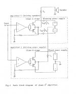
You, perhaps, have introduced completely different issue about Technics class A+ amp. If that is the case, then you talking about a different animal. Basically, in this design you get 2 output stages, a regular class AB O/P and then a tiny class-A amp . In effect, any x-distortion is get corrected by the small class A amp. The working principle is unique. Basically the composite collector current profile , both from class-a and ab, is a result of amalgamated profile and the end result is: you get almost x-over free or any other rail induced artifacts free output. Bear in mind that, typical class-AB amp has a nasty element of rail induced x-over artifacts as Mr Cordell hinted in his explanation in another non-swtiching class B post.
The japanese engineers recommended that this type of design should be realised in an amp from 80W and above. Pls note that this topology yields about 50% of efficiency compared to 25% in a pure class-A and about 77% in AB design. Many of our forum gurus have concluded that, this topology is one of the most robust solutions to the journey towards high efficiency class-a design avaialble to date . Also ,IMHO, static type of x-over distrotions that Mr Cordell cited in his post could be completely eliminated in this type of non class-A design.
Cheers.
I didn't quite get it...I was asking for a design concept , not a copy of anyone else's complete design work.
You, perhaps, have introduced completely different issue about Technics class A+ amp. If that is the case, then you talking about a different animal. Basically, in this design you get 2 output stages, a regular class AB O/P and then a tiny class-A amp . In effect, any x-distortion is get corrected by the small class A amp. The working principle is unique. Basically the composite collector current profile , both from class-a and ab, is a result of amalgamated profile and the end result is: you get almost x-over free or any other rail induced artifacts free output. Bear in mind that, typical class-AB amp has a nasty element of rail induced x-over artifacts as Mr Cordell hinted in his explanation in another non-swtiching class B post.
The japanese engineers recommended that this type of design should be realised in an amp from 80W and above. Pls note that this topology yields about 50% of efficiency compared to 25% in a pure class-A and about 77% in AB design. Many of our forum gurus have concluded that, this topology is one of the most robust solutions to the journey towards high efficiency class-a design avaialble to date . Also ,IMHO, static type of x-over distrotions that Mr Cordell cited in his post could be completely eliminated in this type of non class-A design.
Cheers.
Attachments
OS,
Good luck with your new blend of class A flavour.
Why only limited to 20 trannies? You could lift your barrier and use as many as you want, some of them can act in slave mode not in active configuration as one might imagine. These days they come very cheap..
Anyway, thanks for your answer.
Atiq
Good luck with your new blend of class A flavour.
Why only limited to 20 trannies? You could lift your barrier and use as many as you want, some of them can act in slave mode not in active configuration as one might imagine. These days they come very cheap..
Anyway, thanks for your answer.
Atiq
Why only limited to 20 trannies? You could lift your barrier and use as many as you want,
I could go 20-24 (even 30) but I want to keep it "doable"
for newbies .The vast majority will opt for the simple and
elegant design... FA1 ,Quasi amp ,DX..etc..
OS
In that case you could offer 3 different variants: beginners/moderate/advanced version.You already run quite a few simulation options.
Cheers
Cheers
OS,
when would you like to share your (technics) diode controlled class-a design? can you elaborate this idea??
when would you like to share your (technics) diode controlled class-a design? can you elaborate this idea??
atiq,
Is yours an example schematic from one of those japanese harmonic canceling amps? Can you briefly explain it's workings?
Os, having 3 types of amp frees you from imposed constraints associated with builders but I do understand your concerns.
Is yours an example schematic from one of those japanese harmonic canceling amps? Can you briefly explain it's workings?
Os, having 3 types of amp frees you from imposed constraints associated with builders but I do understand your concerns.
atiq19, no Im not going that route but it does look good except for even more complexity, technics have 2 schemes, one is new class a the other is class aa, I think the scheme you showed is like the aa type, unfortuneatly I cannot see the document proposed by jkenny, this might be interesting as this is the route I took but bear in mind that this is not possible without a non switching scheme in the first place, or so I found.
The design concept is to try eliminate high even and uneven order distortions in outputstages, this has been worked on by others, the easiest to see how this works is to see an example of someone elses work and what they tried to achieve and why I gave the mitsubishi amp as reference. Giving design concept schematics is like giving the design away, its easy to work from there, look at Ostripper, he got it, change the resistors to current source etc. Technics secret was out in the open as soon as they gave even the crudedest indication of a design concept schematic.
The design concept is to try eliminate high even and uneven order distortions in outputstages, this has been worked on by others, the easiest to see how this works is to see an example of someone elses work and what they tried to achieve and why I gave the mitsubishi amp as reference. Giving design concept schematics is like giving the design away, its easy to work from there, look at Ostripper, he got it, change the resistors to current source etc. Technics secret was out in the open as soon as they gave even the crudedest indication of a design concept schematic.
atiq - when would you like to share your (technics) diode controlled class-a design? can you elaborate this idea??
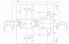
(Attached) WE have to pick the devices/values

Jkeny -Os, having 3 types of amp frees you from imposed constraints associated with builders but I do understand your concerns.
Sort of the FA1 / 2/ 3 idea...🙂
OS
Attachments

ostripper,
When you do your sims on the non switching output stages do you also do a stepped DC input? That is, no AC input but DC at a number of levels until max output voltage is achieved. Then look at the current in the emitter resistors at each step. Repeat for different loads.
When you do your sims on the non switching output stages do you also do a stepped DC input? That is, no AC input but DC at a number of levels until max output voltage is achieved. Then look at the current in the emitter resistors at each step. Repeat for different loads.
Kkeny,
you need to get a copy of the AES paper:
''High efficiency class A amplifier''
Nov 1978, 61st convention.
Here is another thread:
http://www.diyaudio.com/forums/showthread.php?s=&threadid=23590&highlight=
I attached the schematic from 'evolve power amp' website. yes it is japanese.
In simplest term,
lets say we have 50W output of an amp.
8.5W will come from class-A amp contribution.
42W will be taken care of by class-AB.
composite operation is compareable to class-A.
the most subtle feature is rail tracking.
later
Atiq
Steve -When you do your sims on the non switching output stages do you also do a stepped DC input
I do step the input waveform to simulate various levels
(.01, .1, 1, 1.77v) and different frequencies (100, 1k, 10k)
to see if the circuit "holds true". just recently I started using
(2, 4 ,8 ,16R) with capacitance.. to simulate any load
expected.
I will try stepping pure dc, it might help in stabilizing the sourcing
of the class A operation.
Byatiq19 - Here is the concept for Technics class A+.
I think the "new class a" does what amp 1 AND 2 do, but
with 1 Op stage...
OS
No problem atiq, I saw that conceptual schematic with the floating PS on the output - these guys can't even get their head around that concept http://www.diyaudio.com/forums/showthread.php?s=&threadid=137422&highlight=
The whole thread is wasted discussing what floating PS is😕
The whole thread is wasted discussing what floating PS is😕
I have managed so look JVC AX-9 service manual. I don't think this is an elegant solution compared to Technics. I suspect it was probably a marketing hype in 80s. Who would waste 560W idle power for 100W heater?
It would be interesting to see OS realisation of Technics' technique in Frugal amp.
Still, if needed send me pm. File too big (5mb) to attach.
Cheers
It would be interesting to see OS realisation of Technics' technique in Frugal amp.
Still, if needed send me pm. File too big (5mb) to attach.
Cheers
I have managed so look JVC AX-9 service manual. I don't think this is an elegant solution compared to Technics
UPload to my "WWW"...
http://71.203.210.93/upload/~upload
anything else you want to upload ..go ahead..
OS
I think there are posts here about a design flaw in the LT1166 chip - affects the sonics
edit: But I don't know how big n issue - could be worth trying?
edit: But I don't know how big n issue - could be worth trying?
lt1166
jkeny,
http://www.diyaudio.com/forums/showthread.php?postid=1478092#post1478092
http://www.diyaudio.com/forums/showthread.php?s=&postid=1107211#post1107211
read between the lines.
Cheers
Atiq
jkeny,
http://www.diyaudio.com/forums/showthread.php?postid=1478092#post1478092
http://www.diyaudio.com/forums/showthread.php?s=&postid=1107211#post1107211
read between the lines.
Cheers
Atiq
- Status
- Not open for further replies.
- Home
- Amplifiers
- Solid State
- The Frugalamp by OS