Im retiring all my other designs now to the scrap heap. From now on I will only be building this
yes, the M-90 .It really should be the same(sound similar) as the APT as it has almost the same level shifter. It does have 3
poles (compensation) , a lot of playing to get it right.
The Pioneer A-400X is more of a boosted CM with cascoded inputs
Like the VSOP , it uses a diamond to boost the op-amp.
Both these designs use the Be junction of the KSA's
(very miller dependant) while the folded designs
seem to be quite independant of the miller effect.
(much faster as well).
I really did forget to compensate the folded VSOP design ,
I could not do this with a blameless, apt , at least without
making zobel "toast". MJL first noticed the ultimate stability
of this design in the first days of his abomination prototypes.
I even tried mjl/roenders way of compensation (shunt to ground
with 22-33p)and it still works good.
My prototype sounded almost identical to the apt ( simulated
H2/H3 , all others -120db) ,but the Op-amp was cool 😎 for
offset and gain adjustments. with what I have now I can just
make all 3 types of amps , swap them out (modular) to see
which one i want... 🙂 (VSOP is first)
OS
Andy my interest started with the late 70s armstrong design and ended here with Os showing me the M90, the M90 is the baby of this design, there is M7 and M8 only released in Japan, similar front end topology but class A outputs, I havent got schematics on those but some info from a japanese owners. Some of these guys say they have done actual measurements on these amps and report THD20 figures well below 0.001 full power, pioneer were conservative with their measurements. The only thing that botheres me a bit with these designs is the extreme bandwith. Having my cellphone close to it wrecks havoc. Using Jfets in the second LTP also, helps but at the cost of slightly higher THD. The amp as the design is given by pioneer sounds a bit clinical, too precise, but this can be fixed with alternative compensation techniques.
No Miller caps are needed with this design if you choose not to use it , just use degeneration on the second LTP like the armstrong amp. Armstrong schematics are on a thread here. Simulation show stability problems with the armstrong, but real circuit works just fine.
Os, hows the beta matching with those fairchilds in general, anywhere near close ??? I think you forgot to mention. Thd figures like these amps achieve are ridiculously low, you have to push amp to full power to hear the benefit of low THD, I put my nemos and the pioneer circuit blasting through the local discotechs speakers for comparison, mine couldnt handle it and with the pioneer one can notice that the trebles are just a tad cleaner, your ears dont hurt that much after a couple of rounds with metallica, these disco speakers arent good sounding like home based speakers though.
homemodder, I have gone through many piles of the KSA1381/
SC3503 , KSA992/SC1845 , and the new KSP92/42.
Worst case is 5% beta mismatch , out of groups of 20, I can
pair at least half of them (1% or less). the rest I use for
CCS's , Vbe's , etc. (even relay drivers 😀 )
I am going to build one of these (VSOP , MJL's "havoc" , the pioneer , or the APT) I haven't decided yet.
The "ragtag" prototypes I have been throwing together
always work, but for the full sound (power )I want,
only a finished product will do.
If you can submit a schema or .asc of your pioneer clone and
I will simulate it to hell , even make the board for it. 🙂
OS
1 out of 20 at 1percent doesnt sound too bad considering their cost, is this from digikey ???
Ill be getting a pile of 2sa1575 and compl for vas duty in a couple of months time, I just cant get 2sa1406 and compl anymore. Coming from sanyo I will likely be getting 15 pairs out of 20 at 1 percent or better, hence my strong preference for sanyo but at a price disadvantage which offset the percentage matched devices if I was purchasing from other manufacturer. I like the toshibas too but getting close matched pairs is big headaches.
For small signal devices I wont change from 2sa1016k and compl and their dual cousins, still have over 800 factory matched pairs of these I bought for next to nothing 15 years ago, but in this design Im using 2sc3495 and even sanyo jfets.
Os my design Im not revealing, after choosing a pcb these amps will be my next car amps for sale, I been using the tweaked non switching Self type amp for over 9 years and its time for something new, besides this circuit sounds a little better and uses less components, once again I find an amp with wider open loop gain to have better soundstage and I still cannot explain this.
You can play around with the pioneer circuit, linearize each stage especially the second ltp and youll already have very good performance, I just went further and redesigned the vas which is quite different to the pioneer although the same level shifter is used.
All done for now , best sound I have heard yet.
Many hours of readings (Vbias - thermal coeff) ,different flac media, (classical to hard rock) I also invited local church musician
and let my daughter audition.
Between the self amp , vsop clone , the apt and the "secret one"
one amplifier stood out from the others across all genre's and
environments. (the secret one).
What is strange about the secret one is that I threw it in the
junkbox a while back. It is not much of a secret , for it is the
symasym "clone" ..added to a +- 75v PS , a few aska type
compensations , better drivers , and WOW
the best an idiot can create. (schema below).
Amazed at how 9 lowly transistors ( +6 for the OPS)can have no thump at all,
no noise at all , play music down to +- 6v rails and have a better
soundstage than the genesis stealth.
Firing this $30 amp up with a 400$ power supply I'm sure
improves the soundstage , but I used this same PS for all
my other amps and prototypes as well. I know I like when
I let it play day after day and want to try out oldies to hear
"new sounds" that they contain (hidden finger sounds +
other environmental sounds ..)
Full power , endlessly , no heat (those heatsinks don't even get warm at 200W ALL DAY)
😎 😎 I am finally so happy..
OS
An externally hosted image should be here but it was not working when we last tested it.
Many hours of readings (Vbias - thermal coeff) ,different flac media, (classical to hard rock) I also invited local church musician
and let my daughter audition.
Between the self amp , vsop clone , the apt and the "secret one"
one amplifier stood out from the others across all genre's and
environments. (the secret one).
What is strange about the secret one is that I threw it in the
junkbox a while back. It is not much of a secret , for it is the
symasym "clone" ..added to a +- 75v PS , a few aska type
compensations , better drivers , and WOW
the best an idiot can create. (schema below).
An externally hosted image should be here but it was not working when we last tested it.
Amazed at how 9 lowly transistors ( +6 for the OPS)can have no thump at all,
no noise at all , play music down to +- 6v rails and have a better
soundstage than the genesis stealth.
An externally hosted image should be here but it was not working when we last tested it.
Firing this $30 amp up with a 400$ power supply I'm sure
improves the soundstage , but I used this same PS for all
my other amps and prototypes as well. I know I like when
I let it play day after day and want to try out oldies to hear
"new sounds" that they contain (hidden finger sounds +
other environmental sounds ..)
Full power , endlessly , no heat (those heatsinks don't even get warm at 200W ALL DAY)
😎 😎 I am finally so happy..
OS
Hi OS,
Now, try RMI-FC100 ... it was designed as a direct competitor to Symasym, which was my reference in development. Or try abomination 🙂 but if you have jfets, replace the BJT LTP transistors 😉
Those amplifiers will put a very big smile on your face.
THD is not always correlated with SQ 😉
Cheers,
Mihai
No, I built it.. never did any boardwork , then put it in theBy samual - I suspect that you had posted a board layout earlier for this 'secret amp' am I right?
"junkbox". Since it appears this is the "one" I will make
"FA2S" by may 1st. (next mouser order).
By roender -Now, try RMI-FC100 ... it was designed as a direct competitor to Symasym, which was my reference in development. Or try abomination but if you have jfets, replace the BJT LTP transistors
Those are killer designs ..the RMI /abomination. I did try MJL's
new iteration of the RMI and it sounds SO close to this one
with BJT's. Not better or worse but nearly identical. All this
with double the components. I did try the fet differential (attached) and got "silkier" vocals. Used a pair of dual fet's
scavanged from a old pioneer.
With this amp I had to change my method operandi (MO) , no
more relying on simulations and scopes for the final say on the
project. LT shows a small increase in THD20 with both the 10pf
VAS FB and the addition of the cascoded Jfet's. 😕
, but the soundstage/sound is improved. LT is good for avoiding
a catastrophe or seeing what will not work outright , but the
real devices seem to have thier own ideas.
(I initially designed this amp WRONG with the help of LT
 )
)OS
Attachments
Re: All done for now , best sound I have heard yet.
Be careful OS! You're sounding more and more like one of those crazy "audiophiles"!
😀
Pretty soon you'll be buying $1000 speaker cables, a bunch of those little cones to keep the cables off the floor and anit-vibration sorbathane pads to put under all your gear!
It's a slippery slope I tell ya! 😀
ostripper said:I know I like when
I let it play day after day and want to try out oldies to hear
"new sounds" that they contain (hidden finger sounds +
other environmental sounds ..)
Full power , endlessly , no heat (those heatsinks don't even get warm at 200W ALL DAY)
😎 😎 I am finally so happy..
OS
Be careful OS! You're sounding more and more like one of those crazy "audiophiles"!
😀
Pretty soon you'll be buying $1000 speaker cables, a bunch of those little cones to keep the cables off the floor and anit-vibration sorbathane pads to put under all your gear!
It's a slippery slope I tell ya! 😀
Better loudspeakers are due. I now have way more powerBy don -Pretty soon you'll be buying $1000 speaker cables, a bunch of those little cones to keep the cables off the floor and anit-vibration sorbathane pads to put under all your gear!
than any of my sony's can handle. A 10 or 12" peerless
3-way 300watt pair is next.

I already have to take all breakables out of my listening room. 😀
OS
See what I mean?!
HAHA! 😀
I'm looking forward to seeing your new amp all tidy-ed up and ready to rock. It looks like you're close.

HAHA! 😀
I'm looking forward to seeing your new amp all tidy-ed up and ready to rock. It looks like you're close.
ostripper said:I did try the fet differential (attached) and got "silkier" vocals. Used a pair of dual fet's scavanged from a old pioneer.
OS
Specifically which FETs and did you have to make other changes? Iq for BJT vs FET OPS?
By samuel - Specifically which FETs and did you have to make other changes? Iq for BJT vs FET OPS?
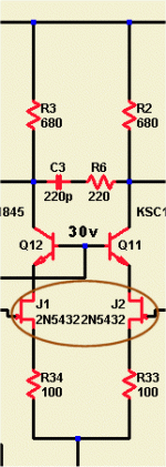
Dual Jfet 2sk129 , possibly obsolete now, in simulation most Jfets
AND mosfet duals or singles work good with proper degeneration.
The rest of the circuit stays exactly the same (the 2 680r's)
just add the 30v cascode , add fet's , "tweak" the degeneration
resistors.
As far as MOSFET outputs , I am serious about making the next board universal ,
accepting both BJT's or vertical MOSFETS (SK-XXX or IRF - XX).
Just add the pads for gate protection ,use 300r-470r gatestoppers.
With 3 pair of my NJW's (on semi) 6-7 A SOA , 8 amps + with MJL
21193/4 , but 10+ for 3 pair IRF MOSFET's. So for obscene
4 ohm power (600W) , the mosfets are the only way ..short of
increasing the number of BJT output pairs.

Re: All done for now , best sound I have heard yet.
The design looks fantastic!!
An additional test is to compare its perceived clarity with a an "ordinary" amplifier (especially compare with one that doesn't have paralleled output transistors). Either outside or on the opposite end of the house will do fine for the test. Clarity at close range is one thing, but clarity at a longer-than-normal range is a different thing. I think its good to check this on powerful amplifiers.
ostripper said:. . .
I let it play day after day and want to try out oldies to hear
"new sounds" that they contain (hidden finger sounds +
other environmental sounds ..)
Full power , endlessly , no heat (those heatsinks don't even get warm at 200W ALL DAY)
😎 😎 I am finally so happy..
OS
The design looks fantastic!!
An additional test is to compare its perceived clarity with a an "ordinary" amplifier (especially compare with one that doesn't have paralleled output transistors). Either outside or on the opposite end of the house will do fine for the test. Clarity at close range is one thing, but clarity at a longer-than-normal range is a different thing. I think its good to check this on powerful amplifiers.
"SUPERSYM"
Just could not think of a better name... 😀
The 8 device PCB design attached will make it even better with 6800uf rail caps and a better CCS (VERY fat current traces).
This amp is the "bomb". I juryrigged 2 more pairs to one of the prototypes and bottomed out my peerless sub.
that happens at 400 watts. With 4 pairs of NJW 0281/0302,I did 50V RMS for extended periods into a 8R load. For 4 ohms,
I did not have any problem pushing the peerless all day , but for straight sine wave testing I would be concerned with SOA.
Even at this power rating , the amp is still cheap (12$ for OPS ,5$ for all the small signal devices , 10$ for all the caps + 20$
for the rest). 50$ X 2 isn't bad for this much power.
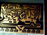
All hand done again , my brother laser printer sucks at making boards but I will make the hand made ones match
the best around here. 😀 (attached)
Just could not think of a better name... 😀
It is similar to Mike B's "symasym" or ampslab Bi240 , just ported out to fit the genesis Stealth PS / case.By DWB - The design looks fantastic!!
The 8 device PCB design attached will make it even better with 6800uf rail caps and a better CCS (VERY fat current traces).
This amp is the "bomb". I juryrigged 2 more pairs to one of the prototypes and bottomed out my peerless sub.
that happens at 400 watts. With 4 pairs of NJW 0281/0302,I did 50V RMS for extended periods into a 8R load. For 4 ohms,
I did not have any problem pushing the peerless all day , but for straight sine wave testing I would be concerned with SOA.
Even at this power rating , the amp is still cheap (12$ for OPS ,5$ for all the small signal devices , 10$ for all the caps + 20$
for the rest). 50$ X 2 isn't bad for this much power.
All hand done again , my brother laser printer sucks at making boards
but I will make the hand made ones matchthe best around here. 😀 (attached)
Attachments
The surround channels.
TDA7294 running cold temps if nearby power caps are smallish (2 of 100nF polypro, 2 of 220uF electro and 1 of 2uF polyester directly at the chip--this in addition to a standard power supply) and when bandwidth is limited to that of the surround speakers. It can minimize heatsink expense and power consumption. This chip is good for small size speakers, such as surround speakers with 5-1/4" or smaller woofers.
26-0-26VAC is slightly over specs for the durability of either chip, and they need an "ac coupled NFB" for safety when operating at or over spec. Its also possible to snub the rectifier with 4 little caps (as with a radio supply) and also use a pair of bleeder resistors. That setup can sink the DC output voltage down by about 2 volts. An additional effect is that this will further cool off the little chip. I don't know why. I'm just reporting on it. The photo below is perhaps more descriptive. 😉
Edit: I hope this is helpful to minimize the heat output of the surround channels section.
Option:ostripper said:. . .The extra 26-0-26VAC is for the two LM3886 rear channel amps. . . [/B]
TDA7294 running cold temps if nearby power caps are smallish (2 of 100nF polypro, 2 of 220uF electro and 1 of 2uF polyester directly at the chip--this in addition to a standard power supply) and when bandwidth is limited to that of the surround speakers. It can minimize heatsink expense and power consumption. This chip is good for small size speakers, such as surround speakers with 5-1/4" or smaller woofers.
26-0-26VAC is slightly over specs for the durability of either chip, and they need an "ac coupled NFB" for safety when operating at or over spec. Its also possible to snub the rectifier with 4 little caps (as with a radio supply) and also use a pair of bleeder resistors. That setup can sink the DC output voltage down by about 2 volts. An additional effect is that this will further cool off the little chip. I don't know why. I'm just reporting on it. The photo below is perhaps more descriptive. 😉
Edit: I hope this is helpful to minimize the heat output of the surround channels section.
Attachments

Is there any IC that can do 36-0-36vDC (that is what I get with bleeders / 10A bridge/4700uf caps). If not ,I have 4 pairs ofBy DWB - 26-0-26VAC is slightly over specs for the durability of either chip,
sanken darlingtons (mn2488/mp1620) that would do for rears.
I want to integrate the power supply/amp on to one board
for each rear channel (just hook up the AC , all done) , and have
at least 40-50w available for my sony 6 1/2" 2-way satellites.
PS , if anyone knows of a good , reliable circuit with low parts count to "use up" my sanken darlington mn2488/mp1620's ,
I would be forever grateful.
OS
Os why not build the same inputstage but modify it for the voltage and the use of those sanken darlingtons. It would be better than any chipamp.
Alternativetly you could build something around lme49811 or its cousin chip with those darlingtons, Im quite impressed with the sound of those chips, way better than any other chips Ive ever tried.
See you find the sound of the sym the best, you have a feedforward cap there which makes makes a big diffs. A amps sound can be changed by the compensation used, as long as its stable. One has to experiment to find the most suiteable compensation for a particular amp.
by homemodder - Os why not build the same inputstage but modify it for the voltage and the use of those sanken darlingtons. It would be better than any chipamp
That is a very good idea. make a to-92 symasym VAS with
Mpsa 92-42's (to keep small) and use the sankens for OPS.
The very high Hfe of the sankens will allow for running the VAS at 2-3 ma. The only thing that worries me is the sound of a darlington amp , I built the elector 60W darlington amp , it sounded like $heet. Both the original sony and the krill are darlington amps , so I know one can sound good.
Another "trick" I see used on the OEM's is 2 470-680p B-C
capacitors to stop oscillations. I guess I will have to prototype
these OPS devices to see what works.
OS
- Status
- Not open for further replies.
- Home
- Amplifiers
- Solid State
- The Frugalamp by OS