ostripper said:
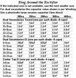
Is there any IC that can do 36-0-36vDC (that is what I get with bleeders / 10A bridge/4700uf caps). . .
RE: Surround channel auxiliary amp.
Yes. LM3886-Parallel It doesn't make typical "chip shout" when parallel because that reduces the "distortion rises with frequency" issue of that chip.
Some of the the "biggie size" version of JRC4560 (on regs) can also be useful (if you don't like big chip power amp sound, just cut the gain and give them a shove with the little clean opamp).
You can probably drop another volt or two by snubbing that bridge rectifier. Chart is attached. In my own use, this has reduced heatsink expense disproportionate to voltage drop. Doing this can let you use LM3886 (solo) / TDA7294 if you wish.
P.S.
Why not make a smaller scale version of the discrete amp pictured in your schematic above? That input section has partial isolation of the input ground, and this is far better than a chip amp's input section.
Although I can't read all of the schematic, I do think that your discrete design will work much better than the chip.
Attachments
Hand made.. but not by a novice.
New boards just etched and stuffed. New technique "electroetch"
(acid and peroxide + 200mA current source - positive to board, negative to a nail in the bath.)
Etched this one in 15 seconds , no pits , no errors. It is cool how
the nail gets coated in copper and the etchant does NOT turn green.
Sharpie super industrial (red lettering) is the best. Regular sharpies can not handle this 15 seconds of electrochemical
magic. Plating is just as easy , reverse polarity (positive on a piece of selenium/silver solder) negative to trace... done.
For plating just make a 10/1 H2O - Hcl mix to make conductive.
I will make a PDF layout of this and a "little bro" (50w version-rears) , I just can't wait to get this done as the prototypes sound
sooo good. I wish someone would take them (prototypes) , I would give them for free to anyone as to not make more E-waste.
They are semi -stuffed , all one would need is the trannies and caps.
OS
An externally hosted image should be here but it was not working when we last tested it.
New boards just etched and stuffed. New technique "electroetch"
(acid and peroxide + 200mA current source - positive to board, negative to a nail in the bath.)
Etched this one in 15 seconds , no pits , no errors. It is cool how
the nail gets coated in copper and the etchant does NOT turn green.
Sharpie super industrial (red lettering) is the best. Regular sharpies can not handle this 15 seconds of electrochemical
magic. Plating is just as easy , reverse polarity (positive on a piece of selenium/silver solder) negative to trace... done.
For plating just make a 10/1 H2O - Hcl mix to make conductive.
An externally hosted image should be here but it was not working when we last tested it.
I will make a PDF layout of this and a "little bro" (50w version-rears) , I just can't wait to get this done as the prototypes sound
sooo good. I wish someone would take them (prototypes) , I would give them for free to anyone as to not make more E-waste.
They are semi -stuffed , all one would need is the trannies and caps.
OS
Oh, It is just the supersym.. 😀
Had to custom make the board to fit the stealth case (Op devices screw into original holes).
Tried to push this amp to clipping , the load 😱 and fuses blew,
put new fuses in and it still worked , need a bigger load.
No speaker in my house can handle this , I guess I need new speakers. It sounds nearly identical to the class A stealth at
moderate listening volumes but when you "crank it" ,breathtaking
is the word to describe it. I could just be listening to the killer
power supply but I did A/B it with a self amp (FA1) , (FA1b - bootstrap) , the genesis and my HT receiver.
Here is final schema (what is going on the board)
Very hardy and stable circuit (listening for 2 weeks now)
Am excited to get this far this fast.
OS
Had to custom make the board to fit the stealth case (Op devices screw into original holes).
Tried to push this amp to clipping , the load 😱 and fuses blew,
put new fuses in and it still worked , need a bigger load.
No speaker in my house can handle this , I guess I need new speakers. It sounds nearly identical to the class A stealth at
moderate listening volumes but when you "crank it" ,breathtaking
is the word to describe it. I could just be listening to the killer
power supply but I did A/B it with a self amp (FA1) , (FA1b - bootstrap) , the genesis and my HT receiver.
Here is final schema (what is going on the board)
An externally hosted image should be here but it was not working when we last tested it.
Very hardy and stable circuit (listening for 2 weeks now)
Am excited to get this far this fast.
OS
Re: Hand made.. but not by a novice.
Hi OS! I'd like to buy them, if I may. . .
ostripper said:I wish someone would take them (prototypes) , I would give them for free to anyone as to not make more E-waste.
They are semi -stuffed , all one would need is the trannies and caps.
OS
Hi OS! I'd like to buy them, if I may. . .
Hi OS! I'd like to buy them, if I may. . .
You don't buy , they are free. If it is you who want them , I will save them for you .
here is pix.
An externally hosted image should be here but it was not working when we last tested it.
You have to wait till my next order comes in , but I will leave the resistors- heatsink/ jumpers. They are FR4 with separate zoble.
They are working right now , so if you populate them as original , a very good amp is possible.
When I tell you , just send a prepaid postal envelope and they are yours. 🙂
OS
ostripper said:
You don't buy , they are free. If it is you who want them , I will save them for you .
. . .
When I tell you , just send a prepaid postal envelope and they are yours. 🙂
OS
Oh I want them! 😀
Send prepaid little box? Well, I'll do it!
There's nothing like a live example sample to speed up my learning, and I think that'll get me "unstuck."
Can you send me your address?
If its okay, I may also send a couple of samples of some more interesting little op amps and audio caps, all sort of frugal, but I think they're fun (point of sending is sharing that fun). At least the little box isn't empty when you get it that way. 😉
I returned your email with the info you requested. As I stated in my email , I will mark the bases and any other missing components for you on the board.
You should be able to mount these on any type heatsink , flat or "L" bracket arrangement will work.
I am not sending you "junk" .. these really crank ! 😀 , even with just 4 OP devices. As far as power goes .. these play music
even when I turn my huge stealth amp off (+ - 75V all the way down to 10V) so any 30-0-30 to 40-0-40 trafo should be just fine.
(live photo attached....) OS
Attachments
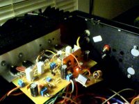
It lives !!!
The suspence , will it work or will I have a pile of burnt sand ? Almost did that , soldered the EMF output diodes backwards ,
,
luckily I powered up with 2 47R resistors (white and green wires).
Right off the bat , with the Vbias and offset trimmers centered,
I got 1.15V between driver emitters (+ - .57v) and 2mv at the
output (wow). BTW , the drivers are acting as the outputs (2 -33R
2w resistors under board).
I was worried about the driver temperatures , but they run rather
cool , even when I crank the bias. The VAS is a reclaimed piece
of roadsign to cool the KSA/C's (perfect warm class A).
I must decide whether to ground the driver heatsinks , I don't
appear to be oscillating , but I want perfection with this one.
Tommorrow I will be able to audition this big symasym after
mounting my 16 OP devices. IT is hard work to build these larger amps.. 😱
PS
An externally hosted image should be here but it was not working when we last tested it.
The suspence , will it work or will I have a pile of burnt sand ? Almost did that , soldered the EMF output diodes backwards
,luckily I powered up with 2 47R resistors (white and green wires).
Right off the bat , with the Vbias and offset trimmers centered,
I got 1.15V between driver emitters (+ - .57v) and 2mv at the
output (wow). BTW , the drivers are acting as the outputs (2 -33R
2w resistors under board).
An externally hosted image should be here but it was not working when we last tested it.
I was worried about the driver temperatures , but they run rather
cool , even when I crank the bias. The VAS is a reclaimed piece
of roadsign
to cool the KSA/C's (perfect warm class A).I must decide whether to ground the driver heatsinks , I don't
appear to be oscillating , but I want perfection with this one.
Tommorrow I will be able to audition this big symasym after
mounting my 16 OP devices. IT is hard work to build these larger amps.. 😱
PS
Today I got all 16 OP devices in and all works well. This is my first 4 pair BJT amp and it brings up a few questions 😕 .
On my 2 OP pair amps I biased by device (12-13mv/.22R - 60ma per device) giving a amplifier total of 250ma. My dilemma is with 4 pair
can I halve the bias per device giving me the same 250ma or is the individual device bias what matters? Simulation says my THD does not change much between 30 and 60+ ma but being in a
hot environment I like cooool.
Also , with the huge heatsinks and 4 pair ,the bias starts out real low (20-25 ma) then slowly increases to 65ma - 18/19mv /.27R ,but this takes a half hour. After this it stays at this level and even backs off a little (1mv) , is this normal and is it caused by the oversized heatsink?
The new amp has .27R emitter resistors (got a deal on 50 of them) and estimated .02C/w heatsinks (stealth class a).
Daniel , if you read this , your prototypes are all cleaned , marked, with a included BOM. Don't feel bad that you have to rebuild it , it won't be anywhere near as labor intensive as this one was and you will learn the ways of the discrete. 😉
OS
On my 2 OP pair amps I biased by device (12-13mv/.22R - 60ma per device) giving a amplifier total of 250ma. My dilemma is with 4 pair
can I halve the bias per device giving me the same 250ma or is the individual device bias what matters? Simulation says my THD does not change much between 30 and 60+ ma but being in a
hot environment I like cooool.
Also , with the huge heatsinks and 4 pair ,the bias starts out real low (20-25 ma) then slowly increases to 65ma - 18/19mv /.27R ,but this takes a half hour. After this it stays at this level and even backs off a little (1mv) , is this normal and is it caused by the oversized heatsink?
The new amp has .27R emitter resistors (got a deal on 50 of them) and estimated .02C/w heatsinks (stealth class a).
Daniel , if you read this , your prototypes are all cleaned , marked, with a included BOM. Don't feel bad that you have to rebuild it , it won't be anywhere near as labor intensive as this one was
and you will learn the ways of the discrete. 😉 OS
Attachments
ostripper said:. . .
Daniel, if you read this, your prototypes are all cleaned, marked, with a included BOM. Don't fell bad that you have to rebuild it, it won't be anywhere near as labor intensive as this on was
OS
Hi man!!! I'm doing a lot of reading and pretty much staying quiet.
Yes, it was just about a week after I got stuck that you posted a design that answers most of my questions. . . except how to build it (I'm not experienced building discrete). 😉
So, I'm REALLY GRATEFUL that you've just up and sent it to me. 😉 As far as assembly, that's not problem--I learn really fast if/when "hands-on."
Thanks again!!! I'm so excited! 😀
you're amp is telling you it is in trouble.ostripper said:Today I got all 16 OP devices in and all works well. This is my first 4 pair BJT amp and it brings up a few questions 😕 .
On my 2 OP pair amps I biased by device (12-13mv/.22R - 60ma per device) giving a amplifier total of 250ma. My dilemma is with 4 pair
can I halve the bias per device giving me the same 250ma or is the individual device bias what matters? Simulation says my THD does not change much between 30 and 60+ ma but being in a
hot environment I like cooool.
Also , with the huge heatsinks and 4 pair ,the bias starts out real low (20-25 ma) then slowly increases to 65ma - 18/19mv /.27R ,but this takes a half hour. After this it stays at this level and even backs off a little (1mv) , is this normal and is it caused by the oversized heatsink?
The new amp has .27R emitter resistors (got a deal on 50 of them) and estimated .02C/w heatsinks (stealth class a).
It could be that the heatsink is too small, not too large.
The tempco is undercompensating and that is resulting in the bias voltage staying too high as the hot output devices lower their Vbe with increasing temperature.
2pair biased to 12.5mVre is equivalent to 114mA of total bias (57mA/device).
If you go to 4pair with the same bias voltage and the same Re then the total bias will be 228mA (still 57mA/device).
BTW,
12 to 13mVre bias is a bit low for an EF output stage. 15mV to 25mV is recommended and the optimum is usually selected by minimising the crossover distortion. Expect this to be around 20mVre.
A 4pair EF output stage should be biased to around 364mA.
Increasing Re to 0r27 will reduce the typical bais to ~300mA. That will demand a large heatsink.
ostripper said:. . . The new amp has .27R emitter resistors . . . OS
Question: If the sum total of the resistors in parallel on the larger scale amp results in a smaller total figure than the smaller scale amp, then doesn't that act like you'd used half value resistors (more heat) on the smaller scale amp?
EDIT: I'm trying to say, maybe since the 2x parallel amp uses 0.22R then the 4x parallel amp needs 0.44R? That and match the output transistors too?
by andrew T. -you're amp is telling you it is in trouble.
It could be that the heatsink is too small, not too large.
Trouble is what I don't want. The heatsinks are 2 of the stealth 7" X 5" thermally coupled together. When I increase to crazy bias (50+ Mv per device) the heatsink still barely gets warm. Originally 2 of these HS's were used for 4 IRF V mosfets biased between 1 and 2A apiece (they got hot then
).What is different on this amp is the fact that I now have the drivers on separate heatsinks. I have seen this on the leach and many other BJT EF amps but again I am on new ground here. When I first turn the amp on The MV's go from 5-6 to 15-16 rather quickly (2 minutes). After that it will slowly rise to 18+mv and stay there overnight(that is where I have it now).
A strange thing I notice is that if I blow on the driver heatsinks the bias will drop for a few seconds and then recover to it's
original levels. Andrew, I did take your advice and I am now shooting for 18-20MV Re.
After looking at the leach for reference , I do have much larger heatsinking by far 😱 for both the drivers and the OP's, how
does the leach do it and is there a reason (drawback or difference) to using separate driver heatsinks? !!
For reference , here is the real timed bias response..
(per device)
Turn on- 7mv
30 seconds- 12mv
1 min - 15mv
2 min - 16.5mv
from 2 min to 30 min - slowly advances to 18+ mv
1 hour on - 18mv + - .1 ( it will drop .1 then go up .1 , etc.)
The 2 X amp has a different Op stage than this one with differentBy DWB - I'm trying to say, maybe since the 2x parallel amp uses 0.22R then the 4x parallel amp needs 0.44R? That and match the output transistors too?
Re's and was set at 13mv X 2 (26mv) which is roughly 60 ma per
device. I used this amp on just 1 stealth HS ,after it thermally stabilized, it stayed + - 1 mv even after a brisk musical session.
I have not done that on this new one yet.
Os
Andrew , you got me worried. So I took a hair dryer and heated the main heatsink to 135 dg. F (with big hairdryer -heatgun, tested w/ new T probe on multimeter) .
The per device voltage dropped to 16mV within 30 seconds, after I removed the heat source, it rose to 18mv after 2 more minutes.
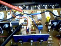
So you know what I am working with , here are the HS's..
And here is where I'm taking my T-comp . from the top of one of the NJW's.
(to-126/2sc2690 - below red probe)
I did a second test and heated the drivers to a similar temperature and kept it there (left heatgun on low).
The mV's went up to 20+ quickly , but did not begin to decrease back to 18+ till after 3-4 minutes. At this time the main heatsinks began to feel warmer. This sort of makes sense as the 2 parts of the EF (driver and OP) have different heatsinking. this is the variable that confuses me with the leach and sloan amps (separate driver HS) does it matter if the Vbe of the drivers is independant of the main OPS/Vbias ?
So I took a hair dryer and heated the main heatsink to 135 dg. F (with big hairdryer -heatgun, tested w/ new T probe on multimeter) . The per device voltage dropped to 16mV within 30 seconds, after I removed the heat source, it rose to 18mv after 2 more minutes.
So you know what I am working with , here are the HS's..
An externally hosted image should be here but it was not working when we last tested it.
And here is where I'm taking my T-comp . from the top of one of the NJW's.
(to-126/2sc2690 - below red probe)
An externally hosted image should be here but it was not working when we last tested it.
I did a second test and heated
the drivers to a similar temperature and kept it there (left heatgun on low).The mV's went up to 20+ quickly , but did not begin to decrease back to 18+ till after 3-4 minutes. At this time the main heatsinks began to feel warmer. This sort of makes sense as the 2 parts of the EF (driver and OP) have different heatsinking. this is the variable that confuses me with the leach and sloan amps (separate driver HS) does it matter if the Vbe of the drivers is independant of the main OPS/Vbias ?
bias current dropping as you force the heatsink temp up is far better than current increasing.
That indicates that tempco is slightly over compensating.
I wonder if the drivers are rising in temp as the amplifier warms up.
That could account for the slow rise in output bias.
Could you temporarily fit bigger sinks to the drivers?
Do they get a good, cool airflow when the case is closed?
from 1min to 30mins it rises from 15mVre to 18mVre. That's not too much variation.
The first few seconds can be ignored, everything is cold and no harm will come from the low bias initially. Almost half the increase comes in 30seconds from cold.
Am I right in calculating that each driver is dissipating 2W?
Are those sinks 20C/W?
I'm trying to design an amp with this topology, I tried such compensation Miller, 2 cap base/collector in Q2 and Q3. But noticed that in 20Khz, IC-Q2 and IC-Q3 are in same phase.
You noticed this?
I removed the cascode and put a resistor...
Regards
You noticed this?
I removed the cascode and put a resistor...
Regards
Under normal circumstances, with the lid off, if your amp takes about 1/2 an hour to reach stable bias, it will do so quicker when you have music playing but then depending on the level of volume, the warm up time will vary and you may not like the slightly 'cold' sound at start-up.
It does appear that your main heatsink is a bit oversized. On the other hand, since it is oversized, why don't you temporarily fit the drivers on the main heat sink with short fly-leads and then check how quickly stable bias is reached? If you find this arrangment better, you might want to leave it that way.
It does appear that your main heatsink is a bit oversized. On the other hand, since it is oversized, why don't you temporarily fit the drivers on the main heat sink with short fly-leads and then check how quickly stable bias is reached? If you find this arrangment better, you might want to leave it that way.
By andrew - Am I right in calculating that each driver is dissipating 2W?
(attached) is the total estimated driver dissipation in mA and the amount of current going to each basestopper. These were simulated whith a worst case 2R load ( beyond the expected SOA of this OPS) In text , the drivers are biased at 24ma idle with a 68R type 2 EF emitter resistor.
I wonder if the drivers are rising in temp as the amplifier warms up.
After the first minute they reach 39C (104 ? F) on my Tcouple , after that ,they stay there. All my tests so far have just been at idle, cooling and heating the drivers and main heatsink as much as I could , the biggest bias variation I could produce was between 15.5 mV and 21 mV and that was done mostly by heating the drivers. the variation was less when heating/cooling the main heatsink.
I think the driver heatsinks are 12.5 C/w

http://www.aavidthermalloy.com/cgi-bin/stdisp_print.pl?Pnum=6021pbg
While looking I also saw the leach driver HS's

They are 21.5 C/W
Mouser sells a "tall boy" version of mine that is 7 c/w if I need more. The 2 amps are mounted vertically with the 4 drivers above a ventilation area (convection). I also have the choice of lowering the bias current of the drivers with a 100R (instead of 68R) emitter resistor. I used this for 2 weeks strait in the prototypes and had no issues , drivers were biased 14mA idle.
OS
Attachments
by samuel -It does appear that your main heatsink is a bit oversized. On the other hand, since it is oversized, why don't you temporarily fit the drivers on the main heat sink with short fly-leads and then check how quickly stable bias is reached? If you find this arrangment better, you might want to leave it that way.
I am only using half of my heatsinks for these 2 amps (4 of the 8 -2 each side) 😀 I did have the prototypes that i'm giving to daniel running , they had the same Vbias but had the drivers on the main HS. The bias started low as with this one , but took 10 minutes to fully stabilize. The bias "curve" was more linear ( 2mv
per minute then 13-14mV final - .22R).
By rafael luc - I'm trying to design an amp with this topology, I tried such compensation Miller, 2 cap base/collector in Q2 and Q3. But noticed that in 20Khz, IC-Q2 and IC-Q3 are in same phase.
I haven't seen that , {attached} is my Q2/3 current phase. It seems to be fully out of phase at 20Khz. if it was not, the CM at
the bottom would not be able to run the vas (would not work). As you can see Q2 is perfectly in phase with the CM. This also seems to hold true at LF , too.
I listened to this one for a while in prototype form , and it really is impressive with cymbals , brushes , especially vocals (abba, WOW) , while it also is very stiff and solid in the bass department as well. Can't wait to hear this one , more refined compensation, matched pairs , more outputs...
, but I must test,monitor,burn in these 2 well before ever hooking a speaker up to it.
OS
Attachments
- Status
- Not open for further replies.
- Home
- Amplifiers
- Solid State
- The Frugalamp by OS