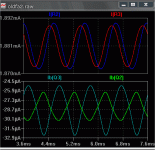
Make in its first stage, 20Khz. Phase in R3 and R2.ostripper said:
I haven't seen that , {attached} is my Q2/3 current phase. It seems to be fully out of phase at 20Khz. if it was not, the CM at
the bottom would not be able to run the vas (would not work). As you can see Q2 is perfectly in phase with the CM. This also seems to hold true at LF , too.
By rafael luc - Make in its first stage, 20Khz. Phase in R3 and R2.
Did that, (attached... first plot) phase is closer but still 10-15 deg., but take a look at Ib Q2 and 3 (second plot) .. totally out of phase. I never really looked at the phase relationship of this amp.
I do have a sim of the "original" symasym. It does the same thing.
I have also replaced the ground referenced cascode with a 15k resistor and noticed the LTP becomes unbalanced along with loss of detail at HF (in listening tests).
I have also tried 10 different compensation schemes that simulated with sufficient phase margin and open loop gain to
come up with what I have. I have also done these "real" to see what audible effects they resulted in.
OS
Attachments
ostripper said:
I do have a sim of the "original" symasym. It does the same thing.
Noted that original symasym, has a peak at high frequency.
In his circuit should not have to 2-Cap Miller
ostripper said:
I have also replaced the ground referenced cascode with a 15k resistor and noticed the LTP becomes unbalanced along with loss of detail at HF (in listening tests).
I think with a cascode, one side is "faster" than other (just a theory). I have also the theory that VAS not working in differential mode.
Which model spice are using to MJE 15032/33. could pass model please.
That my circuit
An externally hosted image should be here but it was not working when we last tested it.
An externally hosted image should be here but it was not working when we last tested it.
An externally hosted image should be here but it was not working when we last tested it.
An externally hosted image should be here but it was not working when we last tested it.
By R Luc- - Which model spice are using to MJE 15032/33. could pass model please.
.MODEL Qmje15032 npn
+IS=3.7344e-10 BF=86.8313 NF=1.23974 VAF=31.5491
+IKF=9.1678 ISE=9.2499e-12 NE=3.28127 BR=5.59346
+NR=1.33161 VAR=2.1791 IKR=5.15023 ISC=4e-13
+NC=4 RB=9.54492 IRB=0.1 RBM=0.1
+RE=0.000568481 RC=0.0931741 XTB=0.737036 XTI=1.04983
+EG=1.206 CJE=3.05969e-09 VJE=0.648491 MJE=0.352663
+TF=4.94819e-09 XTF=1.50001 VTF=1.0001 ITF=0.999982
+CJC=3.00108e-10 VJC=0.600021 MJC=0.40991 XCJC=0.8
+FC=0.534651 CJS=0 VJS=0.75 MJS=0.5
+TR=1e-07 PTF=0 KF=0 AF=1
.MODEL Qmje15033 pnp
+IS=7.51228e-10 BF=134.35 NF=1.25737 VAF=12.5778
+IKF=1.88497 ISE=7.74267e-12 NE=3.34528 BR=5.14173
+NR=1.47488 VAR=1.4505 IKR=7.47186 ISC=3.25e-13
+NC=4 RB=4.37743 IRB=0.1 RBM=0.1
+RE=0.000332989 RC=0.381218 XTB=0.223027 XTI=1
+EG=1.05 CJE=3.06005e-09 VJE=0.64838 MJE=0.352991
+TF=4.78203e-09 XTF=1.50001 VTF=1.00006 ITF=0.999988
+CJC=3.00101e-10 VJC=0.600019 MJC=0.409916 XCJC=0.8
+FC=0.534975 CJS=0 VJS=0.75 MJS=0.5
+TR=1e-07 PTF=0 KF=0 AF=1
Noted that original symasym, has a peak at high frequency.
yes , I did note that .. lead compensation and the RC shunt right on the VAS does that. I actually modeled mine after this...
http://www.ampslab.com/bi120.htm
Also the old hitachi application notes for a simple mosfet amp in 1980,The symasym came along much later in history. As you can see the BI120 is sold out.. 🙂 schema is here..
http://www.ampslab.com/bi120_schematics.htm
But there are no IP issues as I have a different CCS , power devices , comp , layout. Still in the same league.
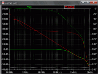
BTW.. here is OLG and bandpass plots (attached)
OS
Attachments
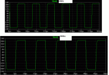
By GK -Stick a square wave into it.
Yes , raphael might have a dandy RF oscillator there 😀
Or some magic smoke...
OLG way too high , no CDOM , no input circuitry.

OS
My circuit not ready...
I posted this to show the graphics
Thanks ostripper by spice model
My output is triple darligton and I must optimize, not ready
I posted this to show the graphics
OLG 30Khz -3dB(~80 fase margin), closed-loop 1.2Ghz 😀OLG way too high
the two capacitors(C3 and C6) are the compensation.no CDOM
I still not didno input circuitry
Thanks ostripper by spice model
I'm working on it, did not sway with resistive load, but presented with capacitive load.Stick a square wave into it
My output is triple darligton and I must optimize, not ready
Hi,
24mA and 75V is ~1.8W in each driver.
12.5C/W sink de-rated by 30% gives deltaTs ~29Cdegrees.
DeltaTc will be ~ 7C higher.
DeltaTj will be ~ 3C higher.
Tj will rise ~ 40Cdegrees from cold when delivering zero output current.
That will explain the sensitivity of the bias to driver temperaure.
Fit two to three times bigger driver sinks. or fit them to the main sinks as suggested by Sam.
2C/W shared by both drivers would be a good start but your PCB may not allow that. This gives deltaTj ~20Cdegrees instead of ~40Cdegrees.
All Done.
WOW, just got through loading this amp down (4 -15" fisher 3 ways). Was able to "bottom out" a woofer while driving 3 ohms.
Andrew , thanks for calculations , I changed my driver Re from 68R to 100R , lowering my driver current to 14mA. This took care of any dissipation problems as well as made my bias stable . I threw AC-DC at it , movies with tremendous bass content , my Pink floyd live
HQ pulse movie (awesome bass -scary).
I was concerned with SOA with paralleled speakers on each channel , but I needed a REAL load for this thing.
Any description of how this sounds would be subjective ,so I won't bother. I can say there is absolutely no hum/buzz , hiss ,
and when I drive 3 ohm's all the way out of one channel , no sound at all in the other channel (PSRR).
Also, less than 5mV offset BEFORE trimming (LTP VR) , now nothing on the inside gets more than 10c above ambient. The main HS's can get rather warm after an hour of obscene levels ,
but now the bias always stays between 18.5 and 20.5mv. 😎
Dan , your box arrived today , and I will pack your 8 caps and 2 boards tommorrow as well as post a pix. 🙂
OS
An externally hosted image should be here but it was not working when we last tested it.
WOW, just got through loading this amp down (4 -15" fisher 3 ways). Was able to "bottom out" a woofer while driving 3 ohms.
Andrew , thanks for calculations , I changed my driver Re from 68R to 100R , lowering my driver current to 14mA. This took care of any dissipation problems as well as made my bias stable . I threw AC-DC at it , movies with tremendous bass content , my Pink floyd live
HQ pulse movie (awesome bass -scary).
I was concerned with SOA with paralleled speakers on each channel , but I needed a REAL load for this thing.
An externally hosted image should be here but it was not working when we last tested it.
Any description of how this sounds would be subjective ,so I won't bother. I can say there is absolutely no hum/buzz , hiss ,
and when I drive 3 ohm's all the way out of one channel , no sound at all in the other channel (PSRR).
Also, less than 5mV offset BEFORE trimming (LTP VR) , now nothing on the inside gets more than 10c above ambient. The main HS's can get rather warm after an hour of obscene levels ,
but now the bias always stays between 18.5 and 20.5mv. 😎
Dan , your box arrived today , and I will pack your 8 caps and 2 boards tommorrow as well as post a pix. 🙂
OS
DAN , DAN .. you didn't have to send me that many parts.. 🙂
Anyways , thank you.
I am giving you the 2 supersym prototypes/+VAS HS's with a nice placement diagram / BOM and tips. Also, 4-3300uf @ 100v caps, 2-10A bridges , 1 - 35A bridge (you could go dual mono or single supply), 2 HS's for little bridges , and 2- GOLD RCA input jacks.
(attached) I would of gave more caps but the weight was too much.
You will have no problems at all , I could have these stuffed and running in an hour, but take your time. I am listening to the "big bro" now and it both takes the blameless's and the OEM's to the cleaners. These don't have the drawbacks of the "iddy bitty" symasyms , bass is strong , but the HF performance is still there with a hell of a lot more headroom. As I stated before, separation is on a dual mono level , I think you will really like these.
OS
Attachments
Yes,Hi,
is post1004 still the current/final schematic?
Yes, except for the change to the driver Re to 100R.
Thank you for ideas ,andrew , I really have this one going nice. 🙂
OS
Here is same (almost) as 1004 but "prettified".
(Schematic is exact as real life amp. )
OS
(Schematic is exact as real life amp. )
OS
An externally hosted image should be here but it was not working when we last tested it.
OS, in the picture that you have posted, there are 4 Output devices per bank, the Vbe transistor is mounted on one of the OPs, the drivers have their own heatsink AND 3 more TO-126 devices are on a flat aluminium heatsink; which of the transistors are these 3, as per your latest schematic?
Thanks.
Thanks.
Hi Sam,
Q4, Q5 and Q8. That right, Pete?
Very pretty circuit.... have you tried decreasing R17/R18 to load up the VAS more and deliver lower OLG, thus reducing fb factor?
I'm sure you have, but remind me please Peter of your findings!
Hugh
Q4, Q5 and Q8. That right, Pete?
Very pretty circuit.... have you tried decreasing R17/R18 to load up the VAS more and deliver lower OLG, thus reducing fb factor?
I'm sure you have, but remind me please Peter of your findings!
Hugh
fb = feedback.
Open Loop Gain / Closed Loop Gain = fb factor, and gives the best indication of how much feedback is applied, and the sorts of error reduction you can expect.
It can be expressed as a number (rare) or as a dB (usual).
Most SS amps use around 30-70 dB of fb.
A Williamson tube amp used 16dB of fb.
A single ended triode typically uses no feedback, that is, 0dB.
- Status
- Not open for further replies.
- Home
- Amplifiers
- Solid State
- The Frugalamp by OS