

is-it so bad?
I will test on veroboard soon
another idea to avoid coupling caps:
put the auto-transformer at the input of the buffer
connect the gates of the output mosfets (keeping the optocoupler bias network and removing R6 and R7) one at each part of R1 on the BFB
Increase the value of R1 until bias of output mosfets is OK
increase power supply to compensate the 10V across R1
Last edited:
Type control L after running the asc file.
You'll get FFT in a text table.
Easier to read.
Patrick
You'll get FFT in a text table.
Easier to read.
Patrick
with 2SB649 more precise model
Harmonic Frequency Fourier Normalized Phase Normalized
Number [Hz] Component Component [degree] Phase [deg]
1 1.000e+03 9.795e-01 1.000e+00 -0.07° 0.00°
2 2.000e+03 4.462e-06 4.555e-06 -89.28° -89.22°
3 3.000e+03 3.609e-07 3.685e-07 -38.43° -38.37°
4 4.000e+03 2.720e-07 2.777e-07 -73.18° -73.11°
5 5.000e+03 2.742e-07 2.799e-07 -71.16° -71.10°
6 6.000e+03 2.798e-07 2.857e-07 -66.50° -66.43°
7 7.000e+03 2.805e-07 2.863e-07 -62.96° -62.90°
8 8.000e+03 2.778e-07 2.837e-07 -60.08° -60.02°
9 9.000e+03 2.857e-07 2.917e-07 -54.81° -54.74°
Total Harmonic Distortion: 0.000462%(0.015468%)
Last edited:
increasing vout to 10V
with TAA004B
Harmonic Frequency Fourier Normalized Phase Normalized
Number [Hz] Component Component [degree] Phase [deg]
1 1.000e+03 9.784e+00 1.000e+00 -0.07° 0.00°
2 2.000e+03 1.129e-04 1.154e-05 -90.06° -89.99°
3 3.000e+03 2.113e-03 2.159e-04 1.70° 1.77°
4 4.000e+03 1.368e-04 1.398e-05 91.47° 91.53°
5 5.000e+03 2.679e-04 2.738e-05 -175.70° -175.63°
6 6.000e+03 5.318e-05 5.436e-06 -86.72° -86.65°
7 7.000e+03 4.556e-05 4.657e-06 3.25° 3.31°
8 8.000e+03 1.166e-05 1.192e-06 86.48° 86.54°
9 9.000e+03 8.037e-06 8.215e-07 -151.64° -151.57°
Total Harmonic Distortion: 0.021854%(0.026769%)
with 2SB649
Harmonic Frequency Fourier Normalized Phase Normalized
Number [Hz] Component Component [degree] Phase [deg]
1 1.000e+03 9.791e+00 1.000e+00 -0.07° 0.00°
2 2.000e+03 2.686e-03 2.743e-04 -88.97° -88.90°
3 3.000e+03 1.302e-03 1.330e-04 3.90° 3.97°
4 4.000e+03 5.882e-04 6.008e-05 92.27° 92.34°
5 5.000e+03 2.915e-04 2.978e-05 -174.17° -174.10°
6 6.000e+03 1.513e-04 1.545e-05 -85.59° -85.52°
7 7.000e+03 7.892e-05 8.060e-06 4.63° 4.70°
8 8.000e+03 3.857e-05 3.939e-06 93.94° 94.01°
9 9.000e+03 2.096e-05 2.140e-06 -164.75° -164.68°
Total Harmonic Distortion: 0.031269%(0.034882%)
Why would you want 10V ?
If that is the requirement, you need to increase the rail voltage to 15V or 18V.
Patrick
If that is the requirement, you need to increase the rail voltage to 15V or 18V.
Patrick
Circuit design groups in semiconductor companies routinely simulate random mismatch of devices on an IC, to get a feeling for what happens when two desired-to-be-identical transistors, do not wind up being perfectly identical. One experiment along those lines might be to use 2SB649A first model for one of the transistors, and 2SB649A second model for the other transistor. Besides the usual Monte Carlo approach of varying the base depth and the emitter area according to some probability density function, then simulating a few thousand random examples to estimate their effect upon circuit performance.
Why would you want 10V ?
If that is the requirement, you need to increase the rail voltage to 15V or 18V.
Patrick
to put the gain transformer at the input of the BFB and drive the mosfets directly across the R1 of BFB withput couling caps
yes of course increasing the supply to 18V, modofy the value of R1 and remove R6 R7 on the M2X and maybe the D1 D2 D3
Feasible? or stupid idea?
of course it wont be an F2X anymore
They have enough manpower, and they make thousands, if not millions of units of one single product.
I rather spend my time matching.
Patrick
I rather spend my time matching.
Patrick
The buffer before the transformer is to relieve your signal source from the transformer load.
If your source is powerful enough to drive the transformer, you can skip the input buffer altogether.
Zero distortion, zero power consumption.
Patrick
If your source is powerful enough to drive the transformer, you can skip the input buffer altogether.
Zero distortion, zero power consumption.
Patrick
M2X - BlackForestBuffer
Good evening,
I made some progress with the Black-Forest-Buffer:
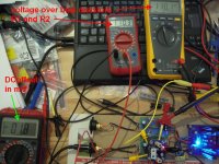
I have made a lot of tests yesterday and this evening. I tried to dial in the DCoffset on both bufferboards. It was pretty easy, to get it below 10-15mV.
DCoffset was fluctuating a bit.
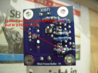
Then I've got the tip from Patrick to put the R2 and parallel R2trim-pot(bias resistor lower half) out and to solder a 2.7Ohm resistor in.
And voila! Very low offset (3mV and 1.8mV on the other board).
So, my matching of the JFets and the TTA004 can't be so bad? 🙄
Some pics from my 'journey'.
Greets
Dirk 😀
Good evening,
I made some progress with the Black-Forest-Buffer:
I have made a lot of tests yesterday and this evening. I tried to dial in the DCoffset on both bufferboards. It was pretty easy, to get it below 10-15mV.
DCoffset was fluctuating a bit.
Then I've got the tip from Patrick to put the R2 and parallel R2trim-pot(bias resistor lower half) out and to solder a 2.7Ohm resistor in.
And voila! Very low offset (3mV and 1.8mV on the other board).
So, my matching of the JFets and the TTA004 can't be so bad? 🙄
Some pics from my 'journey'.
Greets
Dirk 😀
Attachments
The trimpot was causing your DC drift earlier.
That is why I don't use them.
You would have gotten the same result as you do now with 3.3R // 15R fixed resistors.
Patrick
That is why I don't use them.
You would have gotten the same result as you do now with 3.3R // 15R fixed resistors.
Patrick
The PCB layout is not 100% the same as the asc file.
For layout convenience, I changed the DC trimming to R2.
No performance impact at the lower CCS, not the driver.
Patrick
For layout convenience, I changed the DC trimming to R2.
No performance impact at the lower CCS, not the driver.
Patrick
Don't forget the trimpot on the M2x amplifier "mother" board. It adjusts the DC offset at the output of the amplifier, i.e., across the loudspeaker terminals. Nelson Pass put it there but in DIY you can build it any way you like.
M2X - BlackForestBuffer
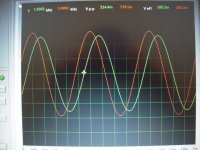
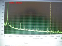
I also made a 'fast and dirty' measurement with my simple PC-oszi.
I have sent a 1kHz - sinus at circa 0.6V through that little thingie...
I know - this is not a professional measurement. Please be patient with me😕
Greets
Dirk
I also made a 'fast and dirty' measurement with my simple PC-oszi.
I have sent a 1kHz - sinus at circa 0.6V through that little thingie...
I know - this is not a professional measurement. Please be patient with me😕
Greets
Dirk
Attachments
Can a speaker level autoformer attenuator be used in place of the Edcor input transformer? I have access to finemet core autoformers with both attenuation levels of 12dB (4:1) and 14dB (5:1). I was thinking of just using them wired in reverse so they step-up instead of attenuate.
Nobody can prevent you from experimenting! Horse around and have some fun.
Maybe you'd enjoy visiting Edcor's website and downloading their specifications for their PC600-15K transformer, including the mechanical drawings and the PCB footprint. This will tell you where the drill-holes for the transformer wires are located on the M2x motherboard, if you don't already have that PCB. Whatever you use to replace the Edcor transformer, will solder into those drill-holes. Perhaps with flying leadwires of course!
_
Last edited:

I have the Edcors on order, however, it looks like in the last few days Edcor has removed the bare pc mount 600:15000 transformer from their website (the page from my history now loads an error). It looks like one has to purchase the 600:15000 pre-mounted on a PCB that Edcor supplies. There is an attendant price increase as well.
It looks like Edcor is re-organizing their website and hasn't yet finished the job. Just now (15 March 1700 Pacific Daylight time in San Jose) I was able to successfully visit these links -- which all worked fine for me:
the "PC" series of matching transformers
the product called "PC600/15K"
the mechanical drawing and PCB footprint of PC600/15K
the "PC" series of matching transformers
the product called "PC600/15K"
the mechanical drawing and PCB footprint of PC600/15K
- Home
- Amplifiers
- Pass Labs
- The diyAudio First Watt M2x