leave 5K timpot in place , just dial it all the way on other side
meaning of my post was not making "cover it all" solution ( which Mark already gave) but to help you in your situation
if you need lesser displacement of offset setting ( again - for your case only!) , use 470K as parallel cure
meaning of my post was not making "cover it all" solution ( which Mark already gave) but to help you in your situation
if you need lesser displacement of offset setting ( again - for your case only!) , use 470K as parallel cure
Hmm ok I did not remove the 5k trimmer and tried to power it thinking only R6 value making change is sufficient. I think I should anyway replace the 5k trimmer to 20k to get the required offset in right position then.
Thanks
If you use some chip quick or equivalent specialty low melt point solder it will make removing the pots much easier.
Manged to remove the 5k trimmer and replaced it with 20K one and with R6 paralleled with 220k I am able to dial the offset to 0.3mV and pretty stable 🙂
One channel is cooking will make the same change of trimmer on the other channel as well.
Thanks all.
One channel is cooking will make the same change of trimmer on the other channel as well.
Thanks all.
An hour in the library can often save a month in the laboratory
Very true Mark 🙂
I almost did this myself and I used someone else's BOM. I think one of the part numbers might of changed with Mouser, luckily I caught it after comparing the Mouser final invoice to the schematic (I labelled the parts on order).Mosfets are fine and isolated from the heat sinks. Found the culprit and its me who used a 221k instead of 220R resistor on R11. Changed it on both the channels and right now cooking. I could dial the offset to -48.1mv when my trimmer ran out of turns and left the channel to run in and i can see that the offset is slowly reducing but still fluctuating. How long does it take to stabilize offset??
Edit: Its stabilized around 0.6mv-10mv range. How much is the bias as I can see that my 300x150x85 heat sinks are running hot within 15-20 mins.
This is one of the reasons why Jim/6L6 strongly recommends you measure every resistor with your DVM, five seconds before you stuff it into your PCB.
Ok both the channels dialed the offset to 0.8-1mV and pretty stable for more than an hour. Set it aside and rechecked ran on my test speakers no issues. Now with temporary housing in my old preamp cabinet it is singing beautifully on my Frugal Horns 🙂
Thanks all.
Thanks all.
An externally hosted image should be here but it was not working when we last tested it.
An externally hosted image should be here but it was not working when we last tested it.
to manniraj
I hope the listening pleasure with your M2X will be a 'payback' for the
hassle you had!
Enjoy the music... 😀
Greets
Dirk

I hope the listening pleasure with your M2X will be a 'payback' for the
hassle you had!
Enjoy the music... 😀
Greets
Dirk
put some spacers beneath heatsinks
they need to breath
Yes sure this is just a temporary housing till I make the chassis ready.
I wonder if the relative high noise figure for the original M2 specified at Firstwatt (500 uV) is caused by noise pickup of the Edcor?
Would it be possible to reach 100 uV by take care of PSU and screen the Edcor?
Has somebody measured noise on the M2X?
Yes, a full report can be found attached to this post.
Cheers,
Alan R.
Attachments
I should have added to my post that the majority of the noise present at the output of the amplifier was 100Hz hum from the power supply, not 50Hz induced hum from the mains toroidal transformer although there was some very small 50Hz component visible on the oscilloscope trace. Yes, I believe the 50Hz component could be reduced by mu-metal shielding over the EDCORE coupling transformers. I did experiment with some steel magnetic shielding strategically placed between the mains transformer and the EDCORE transformers and was able to realise a 2dB improvement at 50Hz. A proper shielding arrangement may very well have achieved better results.
If the amplifier was mine (the test results were taken after a repair / rebuild of a fellow diyAudio's amplifier) I would have seriously considered upping the capacitance in the power supply C-R-C filtering design as IMHO the CMRR of the amplifier leaves something to be desired.
Cheers,
Alan R.
If the amplifier was mine (the test results were taken after a repair / rebuild of a fellow diyAudio's amplifier) I would have seriously considered upping the capacitance in the power supply C-R-C filtering design as IMHO the CMRR of the amplifier leaves something to be desired.
Cheers,
Alan R.
No induced hum out of the channel adjacent to the power trafo?
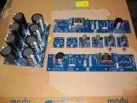
No absolutely no hum at all and this is my 5th power amp build and out of the box with this of chassis and wiring using crocodile clips/jumper wires without any soldering yet. Amazed with this amp being so silent I just used one cable to connect from the psu ground to the chassis ground. All the input RCA and speaker jacks are isolated from the chassis.
... I would have seriously considered upping the capacitance in the power supply C-R-C filtering design as IMHO the CMRR of the amplifier leaves something to be desired.
CMRR or PSRR?
Also, take a look at post #1669, it might interest you.
_
Last edited:
No absolutely no hum at all and this is my 5th power amp build and out of the box with this of chassis and wiring using crocodile clips/jumper wires without any soldering yet. Amazed with this amp being so silent I just used one cable to connect from the psu ground to the chassis ground. All the input RCA and speaker jacks are isolated from the chassis.
Excellent
- Home
- Amplifiers
- Pass Labs
- The diyAudio First Watt M2x