I have two types of .47 ohm 3W power resistors. The usual Panasonic MOX type and Vishay wire wound glazed type that is a bit more robust and has lower temp. drift (75ppm/C vs. 300 ppm/C). When I measure on a bridge they have about same data up to 100 kHz. The wire wound has a bit lower serial inductance…...which was a bit surprising….but noting to "talk about". You prefer the MOX type as source resistor for the output mosfets for subjective "audio" reasons?
Most wirewound resistors exhibit some inductance which in the output stage of the M2x is undesirable as this can lead to high frequency instability in the amplifier. I would suspect the preference for the use of metal oxide resistors is that they have relatively low inherent inductance compared to most wirewounds.
I should add that it is possible to by low inductance wirewound resistors. You just have to check the manufacturer's specifications to ensure the type you are buying are in fact low inductance. I recall the Noble brand being low inductance. Not sure if you can still buy them. I haven't checked lately.
Cheers,
Alan R.
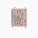
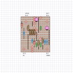
I have drawn up a few IPS designs using 'Vero' or stripboard, including ones for Mtn View and Moffett Field. I actually started with a through-hole version of Tuscon, so I could build the SMD version using the OPA1611, and have a second pair of boards to use for the OPA604 and compatible DIP package opamps. I've included some screenshots of the board layouts, which are all currently un-verified. I am familiar with this style of board construction, having built a few custom pedals for my bass guitar. It is definitely an advanced technique, compared soldering components into a fabricated PCB. But then if a bunch of guitarists can do it, shouldn't be too much trouble for some of the more intrepid amp builders. 🙄
I have taken the liberty of substituting a LM4040-2.5V reference IC for the red LED that is used to bias the current sources. I adjusted the emitter resistors to get the same(?) current used in Mtn View. The Moffett Field design incorporates the ZTX450 "bias dropper," and has the current source set for 20 mA, but may be adjusted by tweaking the parallel 182Ω resistors. I can make more information available once I have verified the board layouts. (Mtn View has a hidden trace cut underneath the 1.0k resistor.)
I have taken the liberty of substituting a LM4040-2.5V reference IC for the red LED that is used to bias the current sources. I adjusted the emitter resistors to get the same(?) current used in Mtn View. The Moffett Field design incorporates the ZTX450 "bias dropper," and has the current source set for 20 mA, but may be adjusted by tweaking the parallel 182Ω resistors. I can make more information available once I have verified the board layouts. (Mtn View has a hidden trace cut underneath the 1.0k resistor.)
Attachments
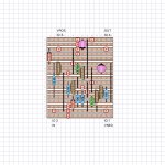
Might want to doublecheck the datasheets of the semiconductor devices in your veroboard layouts. The 2N4416 (middle picture) comes in a TO-18 metal can, not a TO-92 plastic package. There might also be pinout discrepancies in some of the footprints but it's hard to tell.
Since veroboard is single sided copper whereas M2x daughterboards are doublesided, you will have fewer opportunities for the daughterboard to make a reliable electrical contact with the mounting bolt. You might want to consider using Mouser part number 534-7318 to give yourself more opportunities to connect solidly. Solder the wire to the PCB and slip the annulus over the bolt, either below or above the daughtercard. Perhaps both?
These are small enough to go in the same electroplating bath with your mounting bolts, nuts, and star washers, if you decide to plate them with rhodium or gold.
_
Last edited:
Yes, I need to amend my description of the Mtn View veroboard design. In addition to showing a 2N4416 in place of the J112, I also had the 2.048V version of the LM4040, not 2.5V. The emitter resistors in the current sources are set for the 2.048V reference. I have used 2N4416 JFets before in other veroboards. Their metal case pinout is easily adaptable to fit an inline pinout that will match the J112 & J113. The 2N4416 is now available from Linear Systems, and NAC Semi has them in stock. More expensive than the J112, but very good performance. I am in the habit of using three hole sockets for all the small transistors, so it's easy to swap devices. I am still using a 2.5V version of the LM4040 for Moffett Field.
The LM4040 references are available in several voltages and initial precision ratings. For a 2.5V reference, there is also the LT1009, which has better thermal stability and an initial tolerance of 0.2%. Of course these are more expensive than the red LEDs, but hopefully more widely available. If they prove to be suitable for the Mtn View IPS, then it is possible to use them in the existing PCBs with careful installation in the two hole footprint for the LED, and appropriate values for the emitter resistors.
I am concerned about achieving a reliable electrical connections through the mounting holes. Drilling these holes in the correct locations is one of the most difficult aspects of making the boards. I used a bench top drill press and three layers of masking tape to hold two boards in place on a larger piece of MDF that helped the drill bit stay true to the location. Unfortunately, the board I'm using has holes on 0.1" spacing, not metric. I will look at the Mouser part that you mention to see how it might work.
Last edited:
Moffett Field tickled my memory cells. That was the Navy's dirigible base once upon a time.
I'd like to see those old hangars some day.
I'd like to see those old hangars some day.
I powered up one channel today with the PSU showing +/-26.2Vdc on my CRC unloaded. Mounted the Ishikawa daughter board which is what I have built right now. As you can see in the pic I have soldered the cap and the trimmer and did not adjust anything either before mounting or after mounting.
On first power up the DMM on the output pins without anything connected to the input showed +333mv and slowly increasing to 1v and then started to decrease slowly to -12mv and fluctuating to 100-200mv. Didn't adjust the only trimmer on the amp board. Now I see that all the 0.47R resistors (especially R14) getting hot and there was some smoke and immediately switched off. Not sure what went wrong on the parts the mosfets are mounted correctly with little bit of paste and silicon pads. This happened within 1-1.5 mins of powering it up.
Below are the close up pictures of the board. Please let me know what went wrong, as I read that there is no need to use the cap and trimmer on the Ishikawa daughter board. But I think this does not make a change to the bias/offset and this issue.
Thanks
On first power up the DMM on the output pins without anything connected to the input showed +333mv and slowly increasing to 1v and then started to decrease slowly to -12mv and fluctuating to 100-200mv. Didn't adjust the only trimmer on the amp board. Now I see that all the 0.47R resistors (especially R14) getting hot and there was some smoke and immediately switched off. Not sure what went wrong on the parts the mosfets are mounted correctly with little bit of paste and silicon pads. This happened within 1-1.5 mins of powering it up.
Below are the close up pictures of the board. Please let me know what went wrong, as I read that there is no need to use the cap and trimmer on the Ishikawa daughter board. But I think this does not make a change to the bias/offset and this issue.
An externally hosted image should be here but it was not working when we last tested it.
An externally hosted image should be here but it was not working when we last tested it.
An externally hosted image should be here but it was not working when we last tested it.
Thanks
One builder who experienced overheated R13 + R14, traced it to an unwanted metal shard on the heatsink, which pierced the insulating pad and shorted the transistor package to the heatsink.
Another builder who experienced overheated R13 + R14, eventually found out he had stuffed the wrong value resistors in positions R10 and/or R11 and/or R12. This ruined the automatic bias control loop, causing his amp to slowly climb up to maximum possible bias (thus maximum possible heat). This is one of the reasons why Jim/6L6 strongly recommends you measure every resistor with your DVM, five seconds before you stuff it into your PCB.
_
Thanks Mark, let me recheck the mosfets isolation and also the resistor values.
Mosfets are fine and isolated from the heat sinks. Found the culprit and its me who used a 221k instead of 220R resistor on R11. Changed it on both the channels and right now cooking. I could dial the offset to -48.1mv when my trimmer ran out of turns and left the channel to run in and i can see that the offset is slowly reducing but still fluctuating. How long does it take to stabilize offset??
Edit: Its stabilized around 0.6mv-10mv range. How much is the bias as I can see that my 300x150x85 heat sinks are running hot within 15-20 mins.
Last edited:
After running both channels for more than an hour the offset are around channel 1 = -38mv and channel 2 = -139mv with the inputs shorted. Trimmers are at the most extreme and rotating opposite direction increases the offset. I am using matched Toshiba JFETs from alweit as well as matched mosfets IRFP240/9240 on both the boards. Matched in the sense PP/NN.
Channel 2 seems to be a problem with 139-150mv fluctuating offset. Any ideas where to look for as the heat sinks are getting nice hot so everything seems to work fine. The DC rails on the psu are +/-24.v9 to +/-25.4v (CRC) with both the amp boards connected and running with a 0-18v@7A transformer. The DC rails are around 26.4vdc without the amp boards load.
Thanks
After running both channels for more than an hour the offset are around channel 1 = -38mv and channel 2 = -139mv with the inputs shorted. Trimmers are at the most extreme and rotating opposite direction increases the offset. I am using matched Toshiba JFETs from alweit as well as matched mosfets IRFP240/9240 on both the boards. Matched in the sense PP/NN.
....
Thanks
Manni,
Did you look at Step 3 of this post?
Best,
Anand
Oh yes thanks, I did read about that couple of months back when I started ordering the parts but forgot to change the R6 to 37k and also the trimmer from 5k to 20k when soldered. Now the dreaded change of the trimmer needs to be done which is a pain to remove and solder another one in its place 🙁
Anyway thank you very much and know where the problem lies.
just solder another resistor on top of R6 (so in parallel), no need for moving pcb out for that
goal is to go , say, 10% or so down , so use anything between 220K and 330K , what you have in drawer
goal is to go , say, 10% or so down , so use anything between 220K and 330K , what you have in drawer
just solder another resistor on top of R6 (so in parallel), no need for moving pcb out for that
goal is to go , say, 10% or so down , so use anything between 220K and 330K , what you have in drawer
Thanks Zen, you mean 22k - 33k or 220K to 330K.
220K to 330K
in parallel with 47K , that will be 40-ish K
I paralleled a 220k on R6 and when I power the channel the offset starts at around 11V. So immediately switched off. Hence got a doubt. Yes using 220k in parallel the resultant resistance on R6 will be 38.8k. But not sure why does the offset starts at 11v?
Last edited:
to Manniraj
ZenMods advise is good:
47 kOhm in parallel with 220 kOhm resistor = 38,73 Kohm
47 Kohm in parallel with 330 kOhm resistor = 41,14 kOhm
+ 20 kOhm trimpot in series
gives you adjustment range (in case of 220 Kohm) from
38,7 kOhm to 58,7 kOhm.
I hope my little maths are right? 😕
I had the same problem with offset-adjustment at my M2X. (remember the 'blasphemous heresy')
I would change this in the build guide as a general guideline. A few M2X- builders seem to have this problem? Only a thought. Can I think? 🙄
Greets
Dirk
- Home
- Amplifiers
- Pass Labs
- The diyAudio First Watt M2x