Just take the Spice file and replace the TTA004 with those.
BC327 is standard device in LT spice.
Play with the drain resistor values to change bias.
You will find that distortion goes down with more bias.
But dissipation goes up. So there is a balance somewhere.
But you can always use multiple BC327s in parallel to increase bias.
600R (of the transformer) is not exactly a light load.
Patrick
I would do it with 5x BC327-40 parallel to replace 1x TTA004.
Something like this. Will have even less noise.
Still all active parts, still very low costs.
PS
2SK209GR = 2SK117GR (EOL but stiill can be found)
Patrick
.
Something like this. Will have even less noise.
Still all active parts, still very low costs.
PS
2SK209GR = 2SK117GR (EOL but stiill can be found)
Patrick
.
Attachments
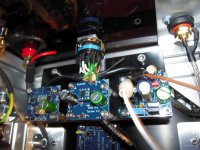
IPS6 - boards stuffed
Hello M2X-builders,
I've got the rest of my parts for the IPS 6 - boards. Stuffed them yesterday.
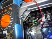
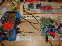
Some adjusting - first on my 'test-rig' than in the amp.....
No listening yet - I can't tell you how it sounds..... 😕 later 😀
Thanks to Mark Johnson for a new inputboard!
Thanks to Ake for the group buy of the pcbs!
Greets
Dirk
Hello M2X-builders,
I've got the rest of my parts for the IPS 6 - boards. Stuffed them yesterday.
Some adjusting - first on my 'test-rig' than in the amp.....
No listening yet - I can't tell you how it sounds..... 😕 later 😀
Thanks to Mark Johnson for a new inputboard!
Thanks to Ake for the group buy of the pcbs!
Greets
Dirk
Attachments
-
 IPS6_adjusting_offset_in_the_M2X_very_close3.jpg118.1 KB · Views: 240
 -
 IPS6_adjusting_offset_in_the_M2X_very_close.jpg123.6 KB · Views: 442
 -
 IPS6_adjusting_offset_in_the_M2X.jpg131.5 KB · Views: 435
 -
 IPS6_adjusting_differential_pair.jpg126.9 KB · Views: 525
 -
 IPS6_parts_stuffed2.jpg84 KB · Views: 521
 -
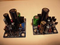 IPS6_parts_stuffed.jpg86 KB · Views: 544
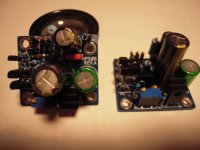
Black Forest Buffer Proto
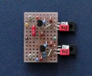
I was curious myself how this would work in reality.
So a quick & dirty Vero proto using what I had in the drawer.
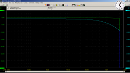
The bandwidth is way beyond 2MHz (my spectrum analyser limit).
But it is also very good at picking up HF noise, from LED lamps, laptop SMPS, ..., etc.
So I put in an RF filter at the input, and also two caps at the BJT to enhance stability.
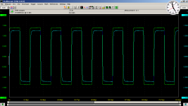
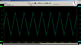
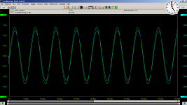
The schematics attached is as built, with 30mA bias.
Also attached frequency response, 100kHz sine, triangle and square, after all the above measures.
QED, 😉
Patrick
.
I was curious myself how this would work in reality.
So a quick & dirty Vero proto using what I had in the drawer.
The bandwidth is way beyond 2MHz (my spectrum analyser limit).
But it is also very good at picking up HF noise, from LED lamps, laptop SMPS, ..., etc.
So I put in an RF filter at the input, and also two caps at the BJT to enhance stability.
The schematics attached is as built, with 30mA bias.
Also attached frequency response, 100kHz sine, triangle and square, after all the above measures.
QED, 😉
Patrick
.
Attachments
to EUVL
Hello EUVL,
measurements look nice! 😀
I still have a few matched Toshiba TTA/TTS 004. I think I should try this?
Greets
Dirk
Hello EUVL,
measurements look nice! 😀
I still have a few matched Toshiba TTA/TTS 004. I think I should try this?
Greets
Dirk
600R, as in the transformer.
Incidentally, the measurements were made when Ri2 was 10k.
Hence the 0.9x gain.
The buffer itself has a Zout of only a few ohms.
Patrick
Incidentally, the measurements were made when Ri2 was 10k.
Hence the 0.9x gain.
The buffer itself has a Zout of only a few ohms.
Patrick
Hello M2X-builders,
I've got the rest of my parts for the IPS 6 - boards. Stuffed them yesterday.
Some adjusting - first on my 'test-rig' than in the amp.....
No listening yet - I can't tell you how it sounds..... 😕 later 😀
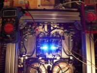
That enclosure looks phenomenal!
Could you post some more pics?
Last edited:
to grataku
Hello grataku,
in this thread - post ## 1327,1340,1403,...
in the thread 'pictures of your diy pass amp': posts #4528, 4536, 4541, 4577...
Greets
Dirk
Hello grataku,
in this thread - post ## 1327,1340,1403,...
in the thread 'pictures of your diy pass amp': posts #4528, 4536, 4541, 4577...
Greets
Dirk
Thanks, looks fantastic. 
I see you setup a switch for the input cards. That's very cool! It takes me ~1h to change out the cards... 😱
I see you setup a switch for the input cards. That's very cool! It takes me ~1h to change out the cards... 😱
EUVL,
could you post actual schematics?
What are these .asc files??
Ditto 😕
Thanks, looks fantastic.
I see you setup a switch for the input cards. That's very cool! It takes me ~1h to change out the cards... 😱
That’s a really neat idea. Food for thought for the next one I build. First one i just finished was destined for the living room but is still in my office/workshop/spare bedroom and I’m loving it so much I’m not letting it go.
Ditto 😕
I think these are netlists for simulations.
Based on the measurements the performance appears to be stellar. it would be nice if there was a more practical or 'buildable' description, at least for me.
😉 🙂
Download LT spice (free).
Open the asc file; press run; and then look at the distortion spectrum with ctrl L.
You will have a lot more fun.
You can also look at DC levels, AC voltages and current at any point on the circuit.
Many tutorials on Youtube.
Cheers,
Patrick
Open the asc file; press run; and then look at the distortion spectrum with ctrl L.
You will have a lot more fun.
You can also look at DC levels, AC voltages and current at any point on the circuit.
Many tutorials on Youtube.
Cheers,
Patrick
+/-24V Rails ?
I was asked whether the BFB can take +/-24V supply directly.
In principle yes.
The 2SK117/2Sk209 are rated at 50V.
The TTA004B even at 160V.
But the limit is the dissipation.
The TTA004 is rated 1W in 50°C air without heatsink.
So 24V 30mA is still OK with a small heatsink.
But the 2SK209 is only rated at 150mW at 25°C.
And not everyone has 2Sk117GRs.
Also, the rails for the power stage are probably not particularly low noise / low ripple.
So it is still better to regulate locally down to +/-12V.
This is how I would make a simple shunt reg, using also the TTA004.
The Vf of the LED will vary, so you will need to trim Rs3.
I have not tested, so build at own risk.
Patrick
.
Attachments
@EUVL,
thanks! WRT rail, we could graft your circuit onto one of the rail-stabilized cards like the IPS7 or IPS8.
I read somewhere here that it is important to keep the power dissipation down on the jfets in order to keep the noise down.
What's a good place to buy the authentic 2sk117GR?
thanks! WRT rail, we could graft your circuit onto one of the rail-stabilized cards like the IPS7 or IPS8.
I read somewhere here that it is important to keep the power dissipation down on the jfets in order to keep the noise down.
What's a good place to buy the authentic 2sk117GR?
Just use 2SK209GR.
It should not be using unobtanium.
I only used 2SK117GR for convenience on Vero.
Patrick
It should not be using unobtanium.
I only used 2SK117GR for convenience on Vero.
Patrick
- Home
- Amplifiers
- Pass Labs
- The diyAudio First Watt M2x