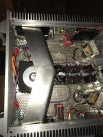
My M2X's are under slight reconstruction. I mount new toriods that should be mechanical noise free. The old had some mechanical humming. To mount the transformer I cut 4 new 4mm threads in the front panel. For that I just used normal hand taps (set of three) and after each I cleaned the hole for metal. "Blind hole" taps could off course be nice. My upgrade of the amp also includes Schurter connector with noise filter. I have some 2A types (these has much more effective filter than e.g. 10A type). To mount these the square hole in the back panel needs to be filed at bit. Therefor back panel has been removed to do this.
The amp I use in the moment is a 300B SE tube amp and Whammy as preamp. 300B still sounds good!
Why the asymmetric arrangement? Is that final position or are you going to center and make everything symmetric?
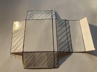
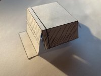
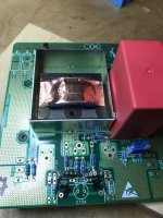
I am pulling a 'Project Binky' fabrication and build a magnetic shielding for the edcor. Here is a pic of the template. It will extend over the board and down to the heatsink for fastening. I bought some 22ga steel sheet at the homestore.
I will probably modify the template slightly and add a four 1/4in lips I can fold over at the corners and solder them.
I will probably modify the template slightly and add a four 1/4in lips I can fold over at the corners and solder them.
Attachments
Something is definitely wrong in the sense that the circuit should be completely 100% adjustable to 0.00 VDC. It may drift in time a by a few mV as you cycle the amp on and off but still...
Do you get to the end of the trimpot? The mods in post 3 only if some of your amp components are so far out as to bring you to the edge of adjustabililty.
Thanks!
Yes, both trimpots are at the end. If I understand post 3 correctly, the problem isn't uncommon, so I think I'll just go ahead and do the modification.
Why the asymmetric arrangement? Is that final position or are you going to center and make everything symmetric?
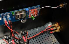
Those are mono blocks. Transformer is placed as far away from Edcor as possible. I have played them for at long time and they were 100% electrical silent but the toroid's began to have some slight mechanical hum. Then I decided to do something about it and ordered Toroidy transformers. They should also be more electrical silent as they have more shields. They also have a PE-wire (yellow green.....but don't know how it is connected internally). But the main reason for the rebuilt was to get rid of the mechanical humming. Then I got some Schurter filters which almost fits in the hole so I make this "upgrade" also. I think it can't hurt. I have measurements from before rebuild so interesting with a measurement after to check if I see any change in noise/distortion.
Attachments
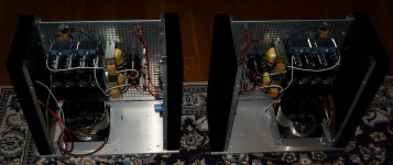
I also have Edcor shielding. I first used copper tape for RF shielding and then mu-metal for magnetic shielding. It goes all the way around. From my distortion measurement the hum level is very low. I also have very low ripple on PSU. Probably the shield does the most and placement of transformer far away.
Attachments
@MEPER Thanks! I see. You used a more complex PS seems to be RCLC with resistors and inductors. Can you share the details? What kind of inductor did you use?
The toroidy looks nice is potted that may help with mechanical hum. What secondary voltage and VA do you use?
Can you hear the difference when shielding the edcor?
The toroidy looks nice is potted that may help with mechanical hum. What secondary voltage and VA do you use?
Can you hear the difference when shielding the edcor?
Thanks!
Yes, both trimpots are at the end. If I understand post 3 correctly, the problem isn't uncommon, so I think I'll just go ahead and do the modification.
OK! there is slightly mismatch somewhere, maybe the output mosfets. Increasing the trimpot range should fix it. My mosfets were close enough and I didn't give it a second thought.
Those are mono blocks. Transformer is placed as far away from Edcor as possible. I have played them for at long time and they were 100% electrical silent but the toroid's began to have some slight mechanical hum. Then I decided to do something about it and ordered Toroidy transformers. They should also be more electrical silent as they have more shields. They also have a PE-wire (yellow green.....but don't know how it is connected internally). But the main reason for the rebuilt was to get rid of the mechanical humming. Then I got some Schurter filters which almost fits in the hole so I make this "upgrade" also. I think it can't hurt. I have measurements from before rebuild so interesting with a measurement after to check if I see any change in noise/distortion.
Will the PSU chokes induce enough EM to affect the input transformer? I know its not AC current (I guess pulsatile would be a better definition?), but I would still like to know if that would be an issue.
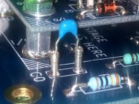
I "socketed" C0, but I'm not sure that was a good idea, as it does not sit "rock solid" in the socket, wobbling a bit if you push it. Though the movement feels being only in the top part, the bottom of the legs still should have contact with the socket nests. Any comments, please? It's my first time attempting this.
Attachments
"wobbling a bit if you push it."
then don't push it! LOL :-D
If you need it you need it soldered otherwise why mess with c0?
then don't push it! LOL :-D
If you need it you need it soldered otherwise why mess with c0?
Wanted to have a way to easily remove it if I decided to use my M2x with the valve pre-amp at sime time in the future. They say it's easier for the valve pre-amps to drive it without the C0 (??) 🙂
Actually, I did not like this "racionalization" with the sockets myself when looking at it, so thinking of removing it and just soldering C0 on the board. But wanted to hear what more experienced people think about that 🙂
Actually, I did not like this "racionalization" with the sockets myself when looking at it, so thinking of removing it and just soldering C0 on the board. But wanted to hear what more experienced people think about that 🙂
With my solder tails, or dip sockets, you can feel the leads get into a position which is more snug in the connection When pushed all the way in. The resistors or capacitors will be a little wobbly because they are on long leads, but they fit snugly in the connection. It may be possible that either your leads are too long or that the Solder tails you are using our two big relative to the diameter of the lead.I haven’t had any problems with my connections but your mileage may vary. I even use my connections to be able to swap out different chips on the input board. You should be able to see this in one of my posts in this thread. Of course, if you’re not comfortable with it you can always just solder the part in or out whether you’re using a tube pre-or not. Again, I haven’t had any problems with mine one way or the other I can add some photos if you wish.
Listening review of new daughter cards IPS6 and IPS7
In case the preceding discussions about metalworking and machine tools have made anyone temporarily forget about the First Watt M2x amplifier, I'm taking the liberty of re-posting some comments made by member avdesignguru. I sent him six free PCBs: 3xIPS6 and 3xIPS7, and he stuffed & soldered those daughter cards, then tried them out in his M2x. I would be pleased to send YOU some free PCBs too; please read M2x post #3416 for the details.
Here are avdesignguru's listening evaluations:
I took advantage of Mark's generous offer of free input boards to those of us who would build and listen to them. Since my favorite M2x board to date was the Tucson with OPA1611, I started with the IPS7. I had some OPA1612 duals (same opamp circuit) so I plugged those in and had a listen. The difference was slight but noticeable. Overall sound character remains the same but the IPS7 has the edge in terms of detail and clarity. The Tucsons were thereby retired.
I had some matched pairs of J113s from a larger lot I bought some time ago. I used pairs that were matched inside the 20 to 21mA Idss range. Perhaps not the more ideal 8-10mA but the whole lot measured 13mA or higher and I went for closer matches rather than lower Idss. The result was very good. I have built all of the input boards except the Norwood and the IPS6 is the best of them all. I still find the M2x more "steely" sounding than the F6 (pun intended) but the M2x/IPS6 and B1Korg is a very listenable combo. I find the F6 with its nickel alloy Jensens stands up better to the scrutiny and intense detail provided by the BA2018 preamp. But that's a different forum.
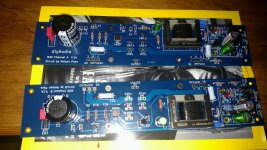
I am building the IPS7 boards you sent this weekend Mark, thanks. I did go through the PCB order process for the IPS6 boards. I tried hard to use use a US fab company. My brother’s fab company only made stuffed boards. The China based company I ended up with charged 1/3rd of what I could find here in USA, and was faster in promised delivery.
IPS7 and Hakuin boards this weekend, will be enough for my attention.
The Toroidy transformers were supposed to ship this week, but, at the last minute, Hubert discovered they had built 220v transformers, not the 115v I had specified. Another delay for the big rebuild. I need these big transformers to plot placement in the chassis, and figure on the switch location on the anticipated black front panel order.
In case the preceding discussions about metalworking and machine tools have made anyone temporarily forget about the First Watt M2x amplifier, I'm taking the liberty of re-posting some comments made by member avdesignguru. I sent him six free PCBs: 3xIPS6 and 3xIPS7, and he stuffed & soldered those daughter cards, then tried them out in his M2x. I would be pleased to send YOU some free PCBs too; please read M2x post #3416 for the details.
Here are avdesignguru's listening evaluations:
I was initially interested in the ips7 but then your post about the opa1611 got me intrigued and made me consider an IPS7 but with the smd traces and DIP traces like the tucson so I am making that PCB version.
- Home
- Amplifiers
- Pass Labs
- The diyAudio First Watt M2x