The idea was that Whammy and BA2018 line stage usually has a very silent PSU compared to the more "rough" PSU in M2X to drive the input boards…..even that some additional components to "smoothen" the PSU has been added. Then maybe a more silent M2X can be achieved? …..even that I am quite satisfied how it runs today with Norwoods…...
You might consider finding a way to temporarily short out resistor R1 on the M2x main amplifier board, when you experiment with straight-wire-bypass of the input stage daughter card. The impedance looking into the primary of the Edcor transformer is 600 to 700 ohms, and that impedance includes a reactive component thanks to the giant capacitive load on the secondary, reflected back to the primary. So you'd like to drive it with as low an impedance as possible. {which some people feel is the reason why Norwood sounds so good: it has a stupendously low output impedance}. Putting R1 = 1 kilohms in series with the output of your upstream audio gear, guarantees that your Edcor transformer will NOT be driven by a low impedance.
With preamps like Whammy and BA2018 linestage (with large output transistors) these should be able to drive Edcor directly. Then I was thinking of an input board which only has the green coupling cap to protect Edcor against DC. Would that work?
Maybe a Tucson board could be modified for that purpose......I have several.
I can confirm that works just fine. I'm doing it driving the M2X directly from a B1-type buffer pre-amp (Mesmerize DCB1). It didn't need a coupling cap, either.
However, make sure the M2X input voltage divider (R1/R2) does not bring down the signal too much -- make R1 something small (or 0R0, if you dare).
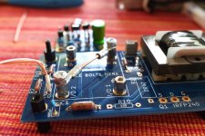
Here's a picture of my IPS "Copper Town". This works nicely for me and it sounds great -- but that doesn't stop me also trying other designs, including the new IPS6 and IPS7 (thank you again, Mark!)
Attachments
Yes, R1 has to be a "short". I think I have 6-7 ohm source resistors on Whammy output stage. BA 2018 linestage I use 15 ohm resistors as far as I remember.....but I now see the advantage of Norwoods that has direct output to Edcor with only a coupling cap to prevent DC.
I put mine on solder tails/DIP sockets. I can switch out according to whatever type of pre I'm using at the time. Easy-peasy.
Ok, that is a nice solution.
If only the green cap is mounted on Tucson board and then a jumber from pin 3 to 6 then Tucson can be used just as DC-blocking passive board?
Even if preamp is almost DC-free when it is up to temp then during warm-up some DC may occur that can "damage" the Edcor. Think I prefer a DC-block cap in front of Edcor. Then input boards could also be moved out of M2X and used as preamp with its own regulated low noise PSU. So no other preamp than the input boards. M2X has enough gain for my use.
Can a 47.5k 1/8 watt resistor be used at position R7?
Just asking because I happen to have some on hand.
Just asking because I happen to have some on hand.
Hi. How hot are the monolithic bridge rectifies during the operation? Does anyone use thermal paste between them and the chassis or is absolutely not necessary?
My bridges are mounted on the opposite side heat sink in the monoblocks. I have previously mounted them to the bottom of the case, as seems to be commonly done. I have never used paste for these. But that doesn’t really answer your question. My anecdotes suggest you don’t need paste.
Not that using paste would hurt anything.
Not that using paste would hurt anything.
Hi. How hot are the monolithic bridge rectifies during the operation?.......
Check out using an LT4320 ‘ideal rectifier’ bridge. There is very little to no heat added to the chassis using this type of rectification. Plus other benefits 😉
Thanks, Bones13 and Vunce. This first time I will go the "traditional" way with the monolithics on the bottom of the chassis. And I will add the paste then, just in case.
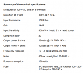
I found this datasheet which contains thermal resistance specifications for the bridge rectifier package "GBPC" as is commonly used in power supplies for First Watt amp clones. It's what I used in my M2x for example.
Maybe someone can put together the math which predicts the junction temperature and case temperature of the GBPC bridge rectifier. Two of these bridges are used (one for DC Vpos, another for DC Vneg), in a Class A power amplifier that draws 160 watts from the AC mains when delivering ± 23 volts DC.
_
Attachments
Pass DIY Addict
Joined 2000
Paid Member
The overall M2 design isn't really a current hog (I < 2A), so you probably don't *really* need any paste between a monolithic rectifier and the case/heatsink.
However, this is DIY and half of the point is to over-engineer things because we can. *Every* amplifier power supply I build uses grease between diodes and chassis/sinks.
Just do it...
However, this is DIY and half of the point is to over-engineer things because we can. *Every* amplifier power supply I build uses grease between diodes and chassis/sinks.
Just do it...
Thanks, Bones13 and Vunce. This first time I will go the "traditional" way with the monolithics on the bottom of the chassis. And I will add the paste then, just in case.
I had my M2x bridge rectifiers mounted to my home made fiberglas power supply board board. They ran at about 65 deg C. Adding about 60 sq. cm of scrap aluminum sheet metal to heatsink them lowered the temp to about 55 deg C. Chassis mounting to any large flat metal surface seems worthwhile and perfectly adequate to significantly extend the rectifier's potential service lifetime.
Thanks, @avdesignguru - that are very valuable real life numbers. Now we know what to expect. It would be very interesting indead if someone knowlegeable could show a theoretical calcuations, as Mark says. I tried to read some pages like this, but its above my understanding yet to apply it to the situation in question.
One thing at least, the data sheet says "Maximum thermal resistance,
case to heatsink RthCS Mounting surface, smooth, flat and greased 0.2".
So, looks like the thermal grease is recommended 😉
One thing at least, the data sheet says "Maximum thermal resistance,
case to heatsink RthCS Mounting surface, smooth, flat and greased 0.2".
So, looks like the thermal grease is recommended 😉
Hi. How hot are the monolithic bridge rectifies during the operation? Does anyone use thermal paste between them and the chassis or is absolutely not necessary?
Initially mine were mounted on the chassis floor but they ran at approx 80C, they are now mounted behind the front panel which is 10mm thick and the whole chassis runs at 50C,
I found this datasheet which contains thermal resistance specifications for the bridge rectifier package "GBPC" as is commonly used in power supplies for First Watt amp clones. It's what I used in my M2x for example.
Maybe someone can put together the math which predicts the junction temperature and case temperature of the GBPC bridge rectifier. Two of these bridges are used (one for DC Vpos, another for DC Vneg), in a Class A power amplifier that draws 160 watts from the AC mains when delivering ± 23 volts DC.
_
Mark,
how did you get the 160W power?
What do you use to properly mount a toroid in a vertical position to the chassis? Is anything suitable available on Mouser, or should I better check my local hardware store?
- Home
- Amplifiers
- Pass Labs
- The diyAudio First Watt M2x