It's in the attachment to post #3432 of this thread. The next-to-last line item.
I am assuming we are talking about M2?
Yes 160W but for M2x 1.3Ax48Vx2=125w
You'd have to add the power dissipated in the residual R of the transformer primary +secondary, and the power dissipated in the bridge but 35W for all that seems a bit much. Hence the question.
What do you use to properly mount a toroid in a vertical position to the chassis? Is anything suitable available on Mouser, or should I better check my local hardware store?
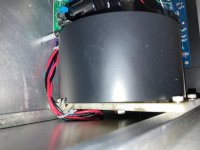
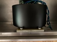
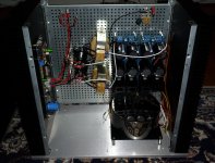
I cut out a piece of G10 I had around, mounted it vertically and drilled a hole for the toroidal in it as shown in pics. Since I have the transformer in the ferrous shielding the base material should be non magnetic to avoid closing the magnetic circuit around the transformer and creating all kinds of tranformer issues.
Given the difference in sound it made I think shielding the power transformer or the edcors or both is a must. The CA case from antek work like a charm. I am working on the the edcor shielding now I bought some steel sheet yesterday.
Attachments
You'd have to add the power dissipated in the residual R of the transformer primary +secondary, and the power dissipated in the bridge but 35W for all that seems a bit much. Hence the question.
You're arguing with Nelson Pass with this question, not Mark. Mark was just quoting the Firstwatt manual.
You're arguing with Nelson Pass with this question, not Mark. Mark was just quoting the Firstwatt manual.
I am not arguing with anybody, just asking a question. 🙂
This is a very interesting question that involves of power factor, the current spike in the rectifier duty cycle and a whole bunch of other very interesting stuff way above my knowledge but that I would like to learn about.
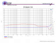
PCW600-15k measurements from Edcor
Free time to build stuff has been nonexistent in the last few months, but I've been doing some thinking about the PC600-15k vs the PCW variant.
This post is a follow-up to my previous post about Scott's 21dB gain configuration, in view of the following posts in an interesting thread containing observations of the PC600-15k when used in the 21dB configuration:
The frequency sweep/THD plot for the 1/2 watt PCW variant isn't on Edcor's website, so I thought I'd post it here. I'm not sure how helpful the data is at only +2dBu, but here it is.
See here and here for some data on the PC600-15k.
Free time to build stuff has been nonexistent in the last few months, but I've been doing some thinking about the PC600-15k vs the PCW variant.
This post is a follow-up to my previous post about Scott's 21dB gain configuration, in view of the following posts in an interesting thread containing observations of the PC600-15k when used in the 21dB configuration:
I like to measure things so I went further and measured the Edcor for voltage swing and for bottom octave behavior.
No problem getting the Edcor to swing 100V p-p undistorted as low as 50 Hz. Below 50 Hz, and above 10 V p-p, there is visible distortion regardless of output impedance of the driver. So, I conclude that the distortion is core saturation.
(emphasis added)Good, let's worry about 20Vpp at 20Hz later. Edcor still has the PCW or the WSM 600/15k that will cut it. Time to start finding out what the PC 600/15k needs to sing well in circuit.
The frequency sweep/THD plot for the 1/2 watt PCW variant isn't on Edcor's website, so I thought I'd post it here. I'm not sure how helpful the data is at only +2dBu, but here it is.
See here and here for some data on the PC600-15k.
Attachments
My M2X is close to completion, but I managed to damage a thread on one of the heat sinks during tapping. But I discovered that there is a solution when accidents like that happen. I acquired a M3 thread repair kit and installed new steel threads. Luckily very easy to do!
Attachments
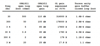
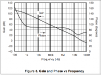
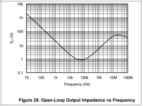
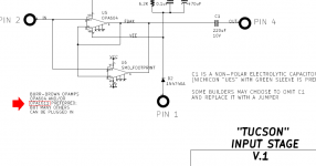
Norwood may not be the only input stage daughter card with extremely low output impedance. Attachments below.
_
Mark,
would you mind explaining how you went from the plots to the table with milli-ohms output impedance?
thanks!🙂
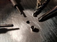
My M2X is close to completion, but I managed to damage a thread on one of the heat sinks during tapping. But I discovered that there is a solution when accidents like that happen. I acquired a M3 thread repair kit and installed new steel threads. Luckily very easy to do!
A solution could also be to fill up with chemical metal and try to tap again. I can see you use a "machine tap"? and not "hand taps" which is usually a set of three taps. They cuts more gently as they cut little by little. Also special taps exists that are made for tapping when it is not a "through hole".
My M2X is close to completion, but I managed to damage a thread on one of the heat sinks during tapping. But I discovered that there is a solution when accidents like that happen. I acquired a M3 thread repair kit and installed new steel threads. Luckily very easy to do!
If you can fix M3 threads you are very good! Too small to deal with for me! 😀
IPS6 and IPS7 Evaluation
I took advantage of Mark's generous offer of free input boards to those of us who would build and listen to them. Since my favorite M2x board to date was the Tucson with OPA1611, I started with the IPS7. I had some OPA1612 duals (same opamp circuit) so I plugged those in and had a listen. The difference was slight but noticeable. Overall sound character remains the same but the IPS7 has the edge in terms of detail and clarity. The Tucsons were thereby retired.
I had some matched pairs of J113s from a larger lot I bought some time ago. I used pairs that were matched inside the 20 to 21mA Idss range. Perhaps not the more ideal 8-10mA but the whole lot measured 13mA or higher and I went for closer matches rather than lower Idss. The result was very good. I have built all of the input boards except the Norwood and the IPS6 is the best of them all. I still find the M2x more "steely" sounding than the F6 (pun intended) but the M2x/IPS6 and B1Korg is a very listenable combo. I find the F6 with its nickel alloy Jensens stands up better to the scrutiny and intense detail provided by the BA2018 preamp. But that's a different forum.
A solution could also be to fill up with chemical metal and try to tap again. I can see you use a "machine tap"? and not "hand taps" which is usually a set of three taps. They cuts more gently as they cut little by little. Also special taps exists that are made for tapping when it is not a "through hole".
Chemical metal is something to try next time! I didn't know there are different taps for through hole and not through holes. I was wondering about that, since the taps I have didn't cut all the way down.
The tap in the photo is part of the repair kit. Before installing the threads the old threads has to be drilled out with a 3.1 mm drill bit, and then one has to tap the hole with the tap supplied in the kit. When that is done, the new threads are screwed in with a special tool.
There is a good illustration here about different taps. The last one is a bind hole. Then the tap is relative flat at the end and made so metal is forwarded up of the hole:
REIME NORIS GmbH >> Taps
REIME NORIS GmbH >> Taps
If you have access to a bench grinder, it is fairly easy to grind a standard style plug tap into a bottom tap. I usually buy two M3 taps at a time. One for through hole, and the second to convert for blind holes.
My M2X's are under slight reconstruction. I mount new toriods that should be mechanical noise free. The old had some mechanical humming. To mount the transformer I cut 4 new 4mm threads in the front panel. For that I just used normal hand taps (set of three) and after each I cleaned the hole for metal. "Blind hole" taps could off course be nice. My upgrade of the amp also includes Schurter connector with noise filter. I have some 2A types (these has much more effective filter than e.g. 10A type). To mount these the square hole in the back panel needs to be filed at bit. Therefor back panel has been removed to do this.
The amp I use in the moment is a 300B SE tube amp and Whammy as preamp. 300B still sounds good!
The amp I use in the moment is a 300B SE tube amp and Whammy as preamp. 300B still sounds good!
Attachments
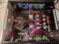
I planned putting everything together the coming weekend, but I couldn't resist. Turned it on for the first time an hour ago. A little scary after having spent a lot of time and money building it. No smoke, fire or explosions so far. I didn't have the correct size Faston connectors for the speaker terminals, so I think I'll just solder them on to ensure a secure connection. Next step is adjusting dc offset and then testing with speakers.
Attachments
I just measured DC offset on both channels:
- Right channel: -47 mV
- Left channel: -12 mV
I couldn't get it closer to 0 than this. Is this a problem? Should I do the modification as suggested in post #3?
- Right channel: -47 mV
- Left channel: -12 mV
I couldn't get it closer to 0 than this. Is this a problem? Should I do the modification as suggested in post #3?
Something is definitely wrong in the sense that the circuit should be completely 100% adjustable to 0.00 VDC. It may drift in time a by a few mV as you cycle the amp on and off but still...
Do you get to the end of the trimpot? The mods in post 3 only if some of your amp components are so far out as to bring you to the edge of adjustabililty.
Do you get to the end of the trimpot? The mods in post 3 only if some of your amp components are so far out as to bring you to the edge of adjustabililty.
Last edited:
- Home
- Amplifiers
- Pass Labs
- The diyAudio First Watt M2x