😱 more than 3 parts in a power supply is too much for my french brain 😀
thanks .
i already have a 2 gigantic CLC in place in my chassis with 1F / 10mh / 1F
sure it is as the opposite of your clever PS but works fine at the end
thanks .
i already have a 2 gigantic CLC in place in my chassis with 1F / 10mh / 1F
sure it is as the opposite of your clever PS but works fine at the end
CLC is best, so keep on with that!
TTSA0300 - Transformer AUDIO TSA300VA - voltage to 50V - Shop Toroidy.pl
TTSA0300 - Transformer AUDIO TSA300VA - voltage to 50V - Shop Toroidy.pl
Question about RV-1
In post #3 Mark mentions alternatively changing R6 to 37K and changing RV-1 to 20K to allow adjustment for those who are having stubborn offset with no pot travel left to adjust. This makes sense, but the next post confuses. #4 says RV-1 is like P3 on F5 turbo, to adjust 2nd harmonic and so forth.
I dont understand how it can be both? I have teabag's M2 boards and one amp has a little offset at end of travel, harmless at 15 mV. I thought of changing the resistor to give "more travel" to the pot, but this idea with 37K and 20K RV-1 sounded great....but not if it causes distortion spectra to vary...
Is RV-1 really like P3? Confused.
Russellc
You have slightly misunderstood post #4. I recommend you read it again, slowly and carefully, paying attention to section headings and expressions rendered in bold text.
Then print out the schematics from their .pdf files attached to post #1, and use a bright neon-yellow highlighter to encircle trimmer potentiometers. Eureka!
_
Then print out the schematics from their .pdf files attached to post #1, and use a bright neon-yellow highlighter to encircle trimmer potentiometers. Eureka!
_
From post #4:
1. Trimmer pot. The 200 ohm trimmer potentiometer RV1 does not appear in the original M2 schematic. But Nelson Pass did include it in subsequent amplifiers (e.g. F5 Turbo), allowing methodical super‐optimization of the phase of the second harmonic, which listeners find extra pleasant. So I put this potentiometer into the M2X schematic and PCB, simply to provide builders that option, if they wanted it. Install RV1 or not, as you wish. (it did say "I included it in the M2X schematic..." so I assumed I was looking at the appropriate RV1. Looking at daughter card schematic, or BOM answers that.
(Editors note (Jim again) You can not adjust this by ear. Get some kind of audio analysis software (ARTA, Electroacoustics Toolbox, etc...) or an old boatanchor distortion analyzer like the HP 339 series, or a spectrum analyzer, so you can actually measure and see the changes in the distortion and distortion distribution.)
Schematic showing daughter card in question does answer question. Two different pots called RV-1. Seeing difference and realizing that the original M-2 is 3rd order dominant (which surprised me to learn) has anyone played with "P3" RV-1 to inject more 2nd order, or alter from original amp's distortion spectra? I'm really liking it as standard but interesting to wonder...this is DIY.
I'm a little in the dark as I have procrastinated setting up a Focusrite w/ REW to analyze such things.
Russellc
Last edited:
Let us know what you find out! Looking forward to hearing about your impressions.
Here’s the link to using REW for the job - Howto - Distortion Measurements with REW
Here’s the link to using REW for the job - Howto - Distortion Measurements with REW
Set up focusrite and REW (Have this same gear sitting here to go next level as well—mic too for speaker/room analysis.) I'd like to know what you find! (tangentially I recently used REW to generate a 15Hz signal to break in some woofers for the OSMC project—way fun.)
I'm having a mythic system experience since adding an Aikido preamp in front of M2X/Norwoods. All the clarity PLUS the soul that seemed to go missing with the substitution of Aleph J (perhaps I like some level of editorializing and sugar?). This isn't an analysis per se of either amp, nor fight'n words—Just my instinctual personal body reaction (family is in agreement though, with no intros from me) —all these NP amps are worth our effort and time. Back to playing and thinking about playing music daily. Also a decided curbing of the desire to keep messing with the setup (This one I will ignore of course 😀) And I did also finally get working a MC cart for the TT—but it's not 100% that change. Maybe 40%—further research required. Something about how music will fill the whole house now from DAC or TT—kinda hard to put into words. "Fullness", "body", "sweetness"? Recordings that I have heard sound really bad with various system iterations sound great—and the "great" recordings put me on the floor... sweetness, but with the extreme clarity of what I might personally associate with H3. I also happen to love the "idea" of Norwoods playing in the mixation with tubes. Point is I guess—preamp seems to have a huge effect on this journey—IMO.
I have no clue what the signatures are of triodes....
I am under the impression that the potentiometer on the Ishikawa daughterboard was for distortion manipulation.
The lowered R6 and an expanded range potentiometer allows wider range of adjustment possibilities to affect the speaker offset.
Did I get it wrong?
The lowered R6 and an expanded range potentiometer allows wider range of adjustment possibilities to affect the speaker offset.
Did I get it wrong?
Bones - you are correct.
The confusion in this case arrives from the nomenclature, specifically that there are two “RV1” ; one on the motherboard, one on Ishikawa.
The confusion in this case arrives from the nomenclature, specifically that there are two “RV1” ; one on the motherboard, one on Ishikawa.
I am under the impression that the potentiometer on the Ishikawa daughterboard was for distortion manipulation.
The lowered R6 and an expanded range potentiometer allows wider range of adjustment possibilities to affect the speaker offset.
Did I get it wrong?
I just hadn't quite figured out that there were two RV-1...I created the confusion, then Marc had answer to look at schematic and there it was.
Russellc
Last edited:
Hi, good people. I just received my ACA kit today, but I am quite confident that the build will be fine, and I already think that I want to plan my next build of some "real" one - like M2X. And I have some questions about that:
1. As I ship it to Europe, I would like to be sure I buy everything I need from DIYaudio store at one time to save the shipping costs. So, next to the PCB kit, should I also buy the LSK170 and LSJ74 pairs (if I want to have parts for Ishikawa)? Ok, they are not so good like Toshiba, but I would hardly be hunting for them, and my amp would still work "as fine" with these substitutes, right? And the BOM is just for one channel, so I have to multiply everything by 2 when sourcing?
2. Power supply. Do I need the Universal Power Supply board from the store also? Is it what M2X needs for power? And what about the power jack, switch, fuse - I have to take care of that myself, right? No recommendations on that? And the BOM for PSU is also just for one half, right?
3. Chassis. What chassis will I need for M2X? Can I buy it directly from HiFi2000 in Italy? What about the drilling of the back pannel? Should I do it myself? Or do HiFi2000 (Modushop) sell some predrilled options? And then all the input output connections on the back - my own business, right?
Could anyone help me to get oriented in all this?
Thanks!
Yes, why not get the LSK, LSJ for Ishikawa? ....get the right grade...
The Universal Power Supply board works very well for M2X and other amps. I use it for M2X.
You can get a connector kit also in DiyStore which fits the cut outs in HiFi2000 Chassis (power, speaker, input). Very nice connectors.
Just order the chassis in the store and store will find out that you should get the chassis directly from Italy. So you pay DiyStore and chassis ships from Italy.
1) LS are fine. Yes. Two pairs. If you get them from the store, they'll be the correct grade (B).
2) UPS is a great option. If you get a back panel parts kit (see #3), it includes an IEC with an integrated fuse block and switch. You'll need to get your own fuses.
3) See Meper's post above. If you choose to get the chassis back panel pre-cut, then I'd recommend going ahead and getting the back panel parts kit. In addition to the back panel parts, it comes with a lot of useful hardware for mounting your boards, FETs etc.
Also, I recommend paying the few extra dollars for an extra set of hardware for the chassis. I'm always losing a nut or bolt...
Thanks, @MEPER and @ItsAllInMyHead.
Do I understand correctly that I need a DELUXE 4U chassis?
I will also need a KERATHERM TRANSISTOR INSULATORS, right?
Back panel parts kit is sold out right now, but I hope that will not be too difficult to source locally, as well as hardware.
Do I understand correctly that I need a DELUXE 4U chassis?
I will also need a KERATHERM TRANSISTOR INSULATORS, right?
Back panel parts kit is sold out right now, but I hope that will not be too difficult to source locally, as well as hardware.
If you are trying to consolidate purchases, yes. Grab some Keratherm.
As an alternative, I like these. You'll also need some thermal paste.
4180G Aavid | Mouser
I use them b/c I swap boards a lot in and out of the same chassis. If you're only going to have the M2x in the chassis and leave it, the Keratherm is a better use of budget IMO.
Edited to add - A 4U Deluxe would be a great chassis for this and potential future builds.
A 4U is fine. I think 6L6 uses a 3U in his build guide?
3U is minimum.
I used 2 x 5U which is overkill but it allowed me to mount large toroid's vertical.
You need to consider how to avoid hum in M2X as Edcor can pickup hum from magnetic fields. If you have very sensitive speakers you need a silent amp.
3U is minimum.
I used 2 x 5U which is overkill but it allowed me to mount large toroid's vertical.
You need to consider how to avoid hum in M2X as Edcor can pickup hum from magnetic fields. If you have very sensitive speakers you need a silent amp.
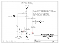
The LED used in the M2x "Mountain View" input stage daughter card, has been annoying M2x builders for quite a while. It just got even worse, after Mouser decided to stop selling individual units of that LED; now their minimum order quantity is 4000 pieces! Digi-Key still sells it in quantity=1, but diyAudio members seem to strongly prefer buying from Mouser.
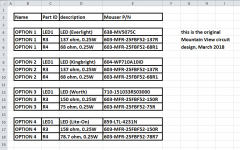
So I bought a bunch of different LEDs from Mouser, made by several top-tier manufacturers, and tested them in Mountain View. The good news is that three of them are quite acceptable and give excellent performance in Mountain View. The not so good news is, the new LED requires slightly different resistor values. It all works in the existing PCB; you just have to buy a matching trio of parts: (an LED ; an R3 resistor ; an R4 resistor). Same board, same schematic, new component values. Have a look at the schematic attached below.
The trio of coordinated parts is (LED1 + R3 + R4). Consult the table of options, attached below, and choose a trio. Then purchase those parts values and install them in your Mountain View boards. Easy! The table of options is presented twice; first as a screen capture image (for easy viewing on the Forum), and also as an Excel spreadsheet inside a .zip archive (for easy copy and paste of cumbersome part-numbers). The component values shown are the results of my lab measurements on Mountain View cards and the three new LEDs.
With three different LED possibilities, there's a MUCH greater chance that your Mouser in your country, will have at least one of them in stock and on the shelf, ready for dispatch. I just checked each of them at Mouser locations which previously were "difficult" (Mouser Finland, Ecuador, Portugal), and these LEDs are in stock & available in quantity=1, today. Nice!
I should mention that the LED and resistors R3 and R4 are not in the signal path of Mountain View; they are simply bias components whose only job is to set the operating currents of signal-handling devices J1 and Q2. Changing the LED has no effect upon the sonic signature of Mountain View. Which I am sure is an assertion that several people will decide to verify or refute, for themselves 🙂
I will work with Forum Moderators to get this information integrated into the official Bill Of Materials for Mountain View.
Mark Johnson
_
Attachments
Appart from the LED and resistors options above, were there any changes in the BOM of the amp board itself and all the buffer boards? Is the BOM attached to the post #1 of this thread up to date?
Mark,
This is very helpful. Thank you so much!
For some strange reason Mouser would not ship the original part to Canada (and
possibly some other countries as well) but it looks like I can order all the substitutes.
Cheers,
Dennis
This is very helpful. Thank you so much!
For some strange reason Mouser would not ship the original part to Canada (and
possibly some other countries as well) but it looks like I can order all the substitutes.
Cheers,
Dennis
- Home
- Amplifiers
- Pass Labs
- The diyAudio First Watt M2x