Nice work Joshua! I like all the high tech addition of Arduino control with temperature and a soft start. Interesting idea to make your own interface board for the input modules. How are the Melbournes working out on the M2X?
@pfarrell,
Do you know what would be a good shielding material that could still be soft or hard soldered? I am thinking of making a small enclosure to surround the edcor and fill it with epoxy.
Do you know what would be a good shielding material that could still be soft or hard soldered? I am thinking of making a small enclosure to surround the edcor and fill it with epoxy.
Do not let these hum issues bother you. <...>
Comparatively speaking, the transformer shielding is a very trivial thing to implement. I don't know where you are but if you get an encased main transformer or an antek with steel enclosure you'll be just fine.
Thank you for encouragement, @grataku! Yes, perhaps I will go with the M2X as initiatialy planned, but will not rush and try to prepare well checking the measurements (that everything fits well into my 4U/300 chassis) and the availability of the boxed main transformer (when I understand better what exactly is needed) etc. This will be some learning curve for me, but that's what we all are here into, I suppose.
I wrapped Edcor with tinned cupper tape and on top of that I wrapped with mu-metal. Doing this Edcor is shielded 360 degree (RF and magnetic shielded). I have very low noise which can be seen from the measurement. 50 Hz is more than 100 dB down. I have seen much worse from "normal" amps. With 94-95 dB speakers I can't hear any hum with ears as close as possible to the speaker units when amp just idles. M2X can be made very quiet.
Attachments

Quick question regarding Ishikawa JFETs...
From building the F5 previously, I suspect the JFETs are supposed to be thermally coupled to each other (e.g. zip tied). But searching a quarter of the way through the thread for photos and doing some text searching I haven't come up with any actual evidence.
Assuming they are supposed to be touching, I wonder how many have been built without the JFETs in contact?
(Fingers crossed I haven't missed something completely obvious on the first page...)
It’s not required at all. (Although it does seem to help a teeny little bit) I kinda wish I never included that in the guides.
...the boards are mounted on an internal fan cooled heatsink near the back...
Hi Josh, your build looks awesome! Would you mind sharing a couple more pics showing your cooling arrangements, it sounds very interesting!
@Joshua
Your amp looks great. I would have to hear that 'zero hum' for myself though particularly since you are running a fan. I found that what other people consider as 'zero'-something or in 'as new conditions' is not so for me... LOL
I would venture the iron shield panel goes a long way in your enclosure. However, I don't believe the M2 needs more than a 200VA trafo. I use an antek AS-2220.
I understand what you mean.
When I say zero hum, I mean full volume and my head stuck inside the horn.
Distance is the biggest effect since the fields drop at the square of the distance. Orientation of the transformers with respect to each other and the iron sheet minimize the rest.
Nelson's original layout puts the Edcors at the edge of the magnetic fields. He used mumetal, which I think is a very good idea for that.
I'll make another post in a moment with more details since another person asked about the cooling.
-Josh
Nice work Joshua! I like all the high tech addition of Arduino control with temperature and a soft start. Interesting idea to make your own interface board for the input modules. How are the Melbournes working out on the M2X?
I made the input module boards because my son and I swapped the boards out constantly while we debated the merits of the ones we liked best.
I love the Melbourne so much, I am in the last stages of assembling an ABBB 🙂
I had to lower the gain on it since it had far too much for my 102dB speakers.
Love this board, and I recommend it to others. It is very tight for space, and expensive, but worth every penny.
-Josh
Hi Josh, your build looks awesome! Would you mind sharing a couple more pics showing your cooling arrangements, it sounds very interesting!
I thought I had taken pics during assembly, but I cleaned out my phone a while back and can't find them.
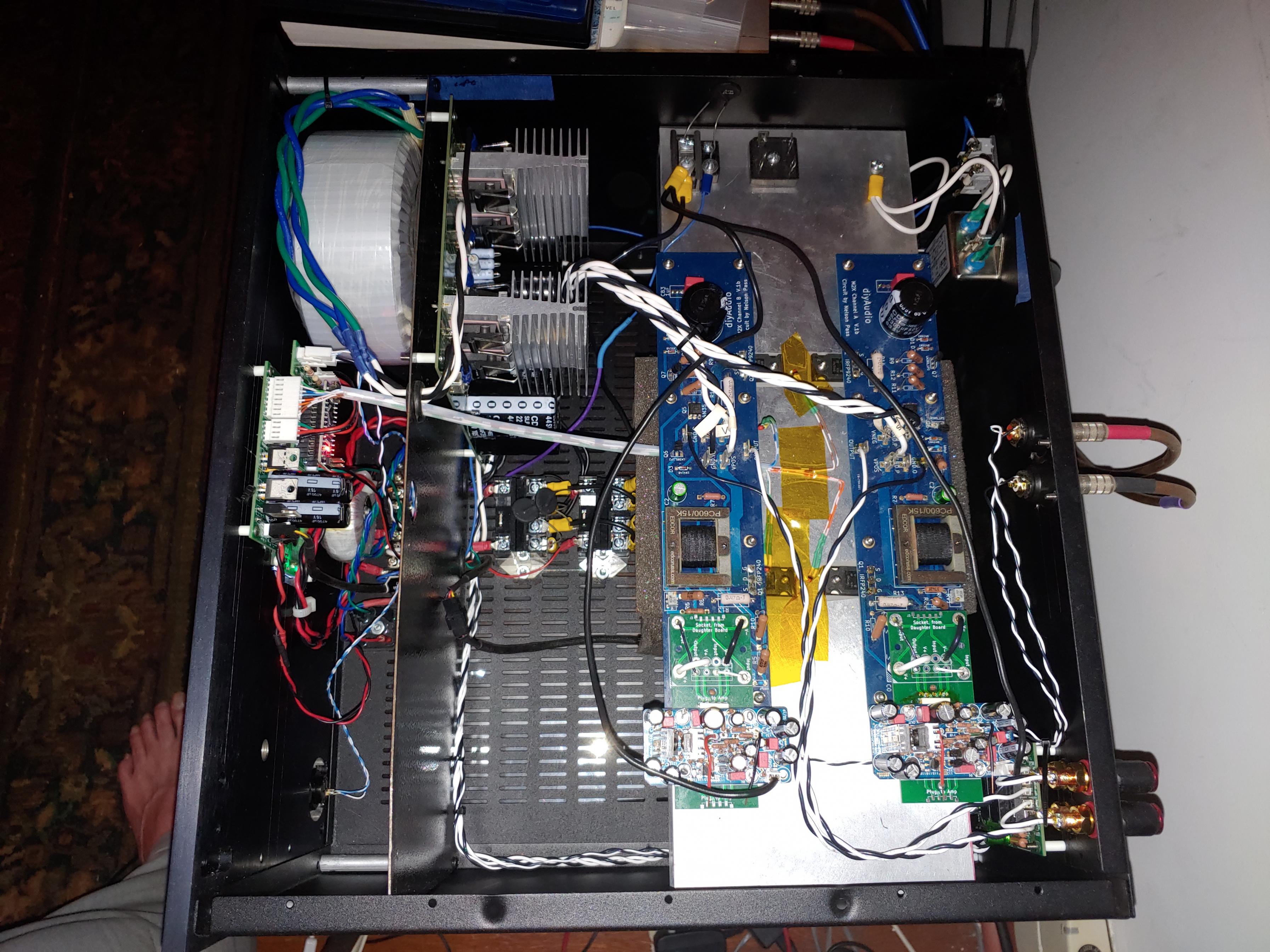
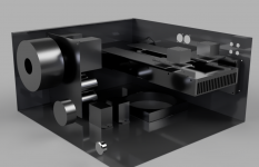
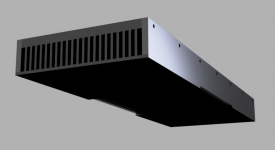
So I made a render of the CAD model, which actually shows everything more clearly, and took a pic looking into the amp obliquely.
The render shows all the major parts except the controller, the display, and the iron divider.
Some details:
When I started the design, I was trying to avoid the high cost of a heatsinked chassis. My original intention was to make the chassis from wood, but I just could not convince myself the fire hazard was worth it. There is also the issue of making a large wooden box remain stable when it has a big heater inside of it. In the end, I used a Pessante 5U 400mm chassis from the store, I saved some money over the cost of a Deluxe, but not a ton.
The heat sink was about $20.00 on Ebay, the aluminum to make the sides and bottom for the heatsink are another $20.00ish, and the fan was something like $25.00. Which is about half the cost difference between the Pessante and Deluxe. I got the material for the divider from an Eppendorf fluid handling robot that got upgraded in the lab next to me. The material is meant for electromagnetic isolation. It is magnetic, but looks like cast aluminum when you cut it with shears.
Designing the heat sink was not hard, I did some math and verified my results with online calculators. I came out about 5% off expected temperature difference.
Still I was not convinced it would work as expected, so I breadboarded up an Arduino with thermocouples to monitor temps while the whole mess was screwed to some MDF scrap.
Putting as much distance between the Edcors and the toroid were at the top my design considerations. After that, I was most concerned with a DC fault circuit and being able to bypass entirely the C-60 thermister used for soft start. At that point, it made sense to stick with Arduino control and engage in some feature creep. I also wanted (if possible) to mount the boards horizontally to make daughter board swaps easier.
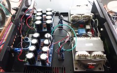
The power supply for the amp is essentially the DIYAudio store board, but space is used more effectively since it is designed to only used discrete rectifiers. I copied and slightly modified the circuit the published by Elliot Sound for the DC protection circuit. By default, the relays in the DC protection circuit are closed so the coils are not energized during use. In the event of a fault, the relays open the amp, and take the speakers to ground. It also sends a signal to the Arduino which will then open the relays that power the amp shutting it down. This essentially means the amp is left to it's own devices in a fault. I have single drivers in my speakers that cost more than this entire project, the amp can catch on fire at this point as far as I am concerned 🙂
When the rear switch is closed, the small toroid gets power and it powers a controller board. The controller board has a 5V regulated supply for the thermistors and display, and a 12V supply for the fan and Arduino. When the front switch is closed, the Arduino ensure the amp is not in cool down (turning the amp off then on again too soon will blow the fuse), too hot, or not in DC fault, then closes the relay with the soft start. After 60 sec, it closes a second relay that bypasses the soft start entirely.
When the amp reaches 60C, the fan is turned on and runs at full speed until the amp cools to 40C. It stabilizes at about 58C. I do not, and see no reason to use PWM. I do not really care what temp it runs at, only that it runs with in an acceptable temp range. I can use a resistor to slow the fan if I want it to run hotter.
The fan itself is mounted to a bracket I made from bent sheet steel on the floor of the chassis.
There are several reasons for adding this complication:
The fan can be removed for service or replacement with out taking anything apart - it is inevitable the blades will get dusty and run out of balance.
Putting distance between the fan and the heatsink substantially reduces flow noise at the fins.
A fan make a round column of air with a hole in the middle where the motor is. Putting distance between the fan and sink allows the air to fill the space better, reduce some of the swirl, and allow the air to enter the sink more evenly.
Not affixing the fan to the heatsink means no vibration is transmitted into the amp board itself.
I made a square tube from closed pore foam to bridge the distance between the fan and sink.
Even at 1:00am when the world is silent, I can't convince myself I can hear the fan run. You can barely hear these big slow Noctua fans running on the desk.
The added time spent putting it all together is offset by 10 second daughter board swaps with out having to fumble with little fasteners in the dark.
I expect this was more than you asked for 🙂
-Josh
Attachments
![0808201155[1].jpg](/community/data/attachments/798/798158-981c870ed5756d4026f3a759c7ebb3a1.jpg?hash=mByHDtV1bU)
![0808201156[1].jpg](/community/data/attachments/798/798185-c6d619eddc6bf3151a838ef7610d2561.jpg?hash=xtYZ7dxr8x)
I understand what you mean.
When I say zero hum, I mean full volume and my head stuck inside the horn.
Distance is the biggest effect since the fields drop at the square of the distance. Orientation of the transformers with respect to each other and the iron sheet minimize the rest.
Nelson's original layout puts the Edcors at the edge of the magnetic fields. He used mumetal, which I think is a very good idea for that.
I'll make another post in a moment with more details since another person asked about the cooling.
-Josh
If you have a passive xover in your speakers the 60Hz PS hum will likely come from the woofers not the horns so much. If it's a ground loop all bets are off. I was talking about 60 Hz from insufficient PS filtration or magnetic interference here.
I made the input module boards because my son and I swapped the boards out constantly while we debated the merits of the ones we liked best.
I love the Melbourne so much, I am in the last stages of assembling an ABBB 🙂
I had to lower the gain on it since it had far too much for my 102dB speakers.
Love this board, and I recommend it to others. It is very tight for space, and expensive, but worth every penny.
-Josh
What are these melbourne and abbb you are mentioning here? Can you post a link?
...
So I made a render of the CAD model, which actually shows everything more clearly, and took a pic looking into the amp obliquely...
Thank you Josh, this is great! BTW, love that you did a 3D model!
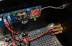
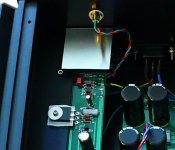
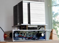
My experience with the Noctua fans is the same, from my listening position I can not really convince myself I can hear it, even if nothing is playing and the house is completely quiet. Not having to rely on passive cooling and huge heat sinks allows a lot more creativity with the setup. To wit, here's my M2X. It even fits into a small shelf space...
I'm using the Noctua NF-S12B redux-700 (no PWM) and also the redux-1200 PWM. The 700 just needs 12V, and its only noise is a faint shush from the slight breeze it creates -- but you gotta put your ear next to the fan to hear it, so don't do that and you'll be fine...
The Noctua NF-S12B 1200 PWM is equally quiet once regulated down, but can produce a lot of airflow when called upon. I agree that PWM is really not needed, except that you can run it at low RPM normally, then turn it up when it's getting hot for some reason, for safety. A little Arduino is taking care of that for me.
In case you were wondering, the power supply is in a separate box out of the way, each channel connected with a 14/4 cable (V+, V-, OUT, GND), and the speakers plug into the PSU box. There's also a F6, ready to be plugged into the same PSU when the mood calls for it (which it does quite often, this is a lovely amp, too!), and soon there'll also be an Aleph J.
Attachments
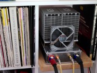

That is a great set up yo have there. I love that huge heatsink. Looks like it came off an old school server.
Have to agree with all you say as well.
I like the idea of external power supplies, they are often the most expensive part of the amp. I decided I would confuse myself after a couple of years and blow something up 🙂
-Josh
Have to agree with all you say as well.
I like the idea of external power supplies, they are often the most expensive part of the amp. I decided I would confuse myself after a couple of years and blow something up 🙂
-Josh
Thank you Josh, this is great! BTW, love that you did a 3D model!
My experience with the Noctua fans is the same, from my listening position I can not really convince myself I can hear it, even if nothing is playing and the house is completely quiet. Not having to rely on passive cooling and huge heat sinks allows a lot more creativity with the setup. To wit, here's my M2X. It even fits into a small shelf space...
I'm using the Noctua NF-S12B redux-700 (no PWM) and also the redux-1200 PWM. The 700 just needs 12V, and its only noise is a faint shush from the slight breeze it creates -- but you gotta put your ear next to the fan to hear it, so don't do that and you'll be fine...
The Noctua NF-S12B 1200 PWM is equally quiet once regulated down, but can produce a lot of airflow when called upon. I agree that PWM is really not needed, except that you can run it at low RPM normally, then turn it up when it's getting hot for some reason, for safety. A little Arduino is taking care of that for me.
In case you were wondering, the power supply is in a separate box out of the way, each channel connected with a 14/4 cable (V+, V-, OUT, GND), and the speakers plug into the PSU box. There's also a F6, ready to be plugged into the same PSU when the mood calls for it (which it does quite often, this is a lovely amp, too!), and soon there'll also be an Aleph J.
Everything is great in this setup...even the Gulda and the Pollini! 😉
Hi. The fresh made DIYer here. I have just finished my ACA without any problems and enjoy it a lot. But I am also already planning my next (and first) "reat" build - M2X.
As I am totaly new in this, sourcing the parts is a major challange for me. Therefore I would appretiate your help very much.
Started from the M2X and PSU BOM and immediately faced questions about the simplest part - resistors. There are no characteristicts (exept resistance itself) provided in the BOM (I suppose any DIYer with even the smallest experience does not need them - but not me).
What type of resistors should I buy? Are metal film resistors fine, or should I go for some special "audio type" here? What should be the tolerance (is 5% fine, or should it be 1%)? What should be the power rating (1/4W, 1/2W) except when specifically marked that some are 3W? Does the size matter (my PSBs are on the way yet, so cannot measure the places live)? In PSU BOM it says "Flame-proof resistor recommended" - how do I know that? What should I look at in the cpecifications?
Lots of questions. Sorry - that's my first time sourcing.
Another question - PSU transformer. Everybody are talking about the Antek here. But as I am in Europe, I would like it to be shipped from some closer location (if not from Lithuania where I am). What would you say about this option?
Triad Magnetics VPT36-6940
Some say 200VA is enough for M2X (though most go for 400VA as I see). This one is 250VA. Also, I will have 4U/300 chassis, so should I care more about the isolation of my tranrformer? Should I look for some boxed version? Or maybe this?
Triad Magnetics VPM36-6940
(same as above, but "medical" grade - better isolation, but 60% more expensive).
Any help is very much appretiated.
-Alvis
Hi Alvis -
Welcome! 😀 Congratulations on your ACA and the decision to move on to a First Watt clone. IMO, you'll be greatly rewarded.
First... even though it sounds intimidating - I strongly encourage you to read the full thread and pull out relevant information. You'll find answers to a lot of questions. In my experience - it relaxed me a bit to read that other people had the same questions.
I know this b/c I was in your shoes. See this post and follow from there re: resistors. 😀
https://www.diyaudio.com/forums/pass-labs/321925-diyaudio-watt-m2x-187.html#post5792894 Post #1863 if the link does not work.
I'd encourage the same level of reading on the PSU thread. There are a lot of suggestions for resistor brands and types. A common one is the Panasonic resistors pictured (the big blue ones). They're now discontinued, and there has been a lot of discussion re: suitable replacements or where to find NOS. We can still get them in the US, but I'm not sure in your region.
This thread below was mentioned just a few pages ago ... It documents my experience through the build. It may help a bit. It should not take long to read, and it specifically notes post numbers in this thread and others with some clipped information provided by others. The summary is at the end, but it may help to read it all. Some fantastic people provided encouragement and knowledge along the way.
A Noob's First First Watt - M2x
re: the power transformers. In general (repeating knowledge shared with me and that I now can grasp); for this build, shielding (both physical with a "can" and internally with a shield between the primary and secondary windings) can lower the potential for the smaller transformers on your amp boards to pick up radiated waves from the power transformer. That, along with the physical orientation (vertical, horizontal, and rotation) and physical distance from the smaller transformers can reduce potential hum. In addition, some people have taken extra measures to enclose the smaller transformers with "mu metal" or similar. I don't have the knowledge to know whether 250VA is suitable for two channels. I've seen this topic often discussed, and will leave it to people with more knowledge than I to make a recommendation and share their reasoning.
Enjoy the journey!
Thanks, @ItsAllInMyHead! You are my big helper here! I have a feeling being of quite similar personality to you as regards to learning, reading, thinking twice (of ten times), compiling information and getting experience from that. That's an amazing journey!
Yes, I did read the ACA threads (main and 1.6/1.8) from the beginning to the end before building my ACA, but M2X thread and PSU thread is really a bit more intimidating (it was just half that big when you initialy read it 😉) But well, I agree, this is a ton of knowleage and most (all) of the questions have been answered there before. So, I will definitely have to dampen my excitment, go back to reading and build my M2X a little bit later.
And thanks a lot for the links in your reply. This helps a lot (though I will come back to that again later, when reading from the beginning 😉). And I did already read your journey into the M2X - very useful and encouraging, though I did not go through all the references in the end yet.
The learning curve is quite steep for a person like me, who took the iron just a few months ago in his 50's 😉 But I have already built my split keyboard, small shelf loudspeakers, two guitar effects pedals for my son, and the ACA. Knee deep in this ocean!
Last edited:
- Home
- Amplifiers
- Pass Labs
- The diyAudio First Watt M2x