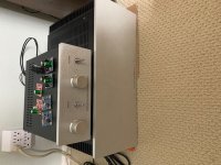
Kitsune Hollow spring dac... Transport is Singxer... This is the lab rig better in the dedicated room.
@delboy,
You should be seeing close to rail voltage on the daughter card two will read almost rail and two ground.
Unplug from the amp board from the supply and check the supply alone, what are your rail voltages? Plug the supply back into the amp and check the rails again at the power supply. For instance I get + - 30volts unloaded and about +- 27-28V plugged into the board. When I test the standoffs to the daughter (Ishikawa) I get slightly less than the rail.
If your rail voltages look okay, then it's time to break out the schematic and go back through everything. Also, I always fire up one side at a time. That way if you hosed something, you don't smoke everything.
If the rail voltages are still good, let us know what you have on the legs of Q1 and Q2
Here are some number off mine to help ya out.
Q1
Gate 5.16V
Drain=Rail or in my case about 28V
Source 738mV
Q2 should be very close to what Q1 is only Neg instead of Pos
Hi,
Thanks for the help. I just measured the amp. Unloaded rail voltages are about +/- 23.4V. Loaded becomes +/- 21.1V to 21.4V.
Left
Q1 D +21.3V
G +5.07V
S +616mV
Q2 D -21.4V
G -5.14V
S -632mV
Right
Q1 D +21.1V
G +5.06V
S +619mV
Q2 D -21.1V
G -5.11V
S -612mV
It seems the main amp board is working? Next I think I should disconnect the Ishikawa daughter board and
- measure the Edcor; hope I have not mis-installed them
- put a signal directly on PIN4 and see if anything gets amplified
Will get back with further results...
Those number are solid db, yes, with my limited knowledge, I would say that board is working, looks to be something in the input. You can't really install the Edcor wrong as the only fit one way as long as you are using Marks' boards.
Okay, I have built these, and or modded these:
BA3
Yarra
Golden Tube 40
F5T V2
J2
AN Monos
Elekit 8600 (With upgrades)
MX2 (Pass spec, or almost)
I love all my kids, but once in a while, you don't need, break in time, if there is such a thing, I think mostly, it's brain/ear acclimatization. All these amps are wicked good, it's hard to say one is better than another, they are all good, and depending on music, speakers and a couple hundred other things, could be happy listening to these forever.
So which one of these has touched my preferences for listening, ears, and brain the most?
I would say M2X for everyday and when I want to pump it up, I would go AN. The Elekit is also friggn amazing for phones or LP play. Damn, I love this stuff... Time to think about building speakers next. I have a couple very good sets, but don't we all look for the ones that just make you opt for pushing sex night back a day? lmao
Anyway, just rambling a bit, so I shall close for now.
JT
Last edited:
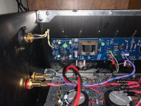
delboy123 - from a couple of your images you are using a cap in C0. Are you sure it’s good? Not shorting the input to the daughter board?
Hi,
Thanks for the help. I just measured the amp. Unloaded rail voltages are about +/- 23.4V. Loaded becomes +/- 21.1V to 21.4V.
Left
Q1 D +21.3V
G +5.07V
S +616mV
Q2 D -21.4V
G -5.14V
S -632mV
Right
Q1 D +21.1V
G +5.06V
S +619mV
Q2 D -21.1V
G -5.11V
S -612mV
It seems the main amp board is working? Next I think I should disconnect the Ishikawa daughter board and
- measure the Edcor; hope I have not mis-installed them
- put a signal directly on PIN4 and see if anything gets amplified
Will get back with further results...
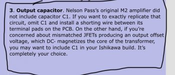
Just a thought regarding the Ishikawa Input boards. Did you instal C1? If you chose not to did you install a jumper as per 6L6’s instructions at the beginning of the thread? I thought I understood, and I may be wrong, that without this jumper you wouldn’t get any sound passing through the daughter board.
Attachments
Last edited:
@JSA That Sir, is a great question, he did post some images of the daughter card and C1 is populated, but still a great idea.
JT
JT
@JSA That Sir, is a great question, he did post some images of the daughter card and C1 is populated, but still a great idea.
JT
Yes you are correct, when I initially looked at the pic it was on my mobile phone and wasn't able to see the pics well. :O
Yes CFP = Complementary Feedback Pair 🙂
The easiest way to add the extra caps would be to use screw terminal can types connected to the extra V+, GND and V- spade lugs on the output of the SLB boards. Or you could use snap in terminal caps wired directly to the SLB boards. Leave the 220 uF caps at C21 and C22 in place. The big caps end up in parallel with these.
Okay, I put in the Caps and gave them a few days of play time. Now this is maybe going to sound strange, but it's honest. I did detect maybe a bit of better lower control, but the thing that had me scratching my head was, the soundstage seems to close down some. I was no longer hearing the voice from all around me... it was focus in between the speakers, but lost much depth.
I thought I must be wrong, how can this be so? I played it for about three days, and just now, I pulled the one lead from each and tapped them off. I turned the amp back on and I immediately heard the stage bloom. I don't understand why, unless possibly the added lower end concealed the mid and upper a bit. Hell I don't know TA, but I trust my ears.
I'll put them back in and run them for a week, or two, but if my impression doesn't change, I will pull them back out for good.
I'm always up for trying something, but so far they, "seemed" to interfere with the lovely imaging. Does anyone have any ideas why this could be so?
If I had to some up my initial thoughts, the thing that comes to mind is the magic had been removed. In case you didn't catch the full story, it was suggested to put KEMET ALS70 on the outputs and that's what I did. They were the 24000uF 40V, so I have 4 of them in parallel with the stock caps.
Last edited:
Your ears are the ones that need to be happy. 🙂
It sounds like you did a good experiment and are getting repeatable results. If these results stay the same, then the right thing to do is what sounds the best.
It sounds like you did a good experiment and are getting repeatable results. If these results stay the same, then the right thing to do is what sounds the best.
Your ears are the ones that need to be happy. 🙂
It sounds like you did a good experiment and are getting repeatable results. If these results stay the same, then the right thing to do is what sounds the best.
Hey TA, I always trust my ears, but I have no reconciliation. Do you have any caps at the lower end of the spectum... I went 24000uF, but did not try something lower... I will not spend another $60, but I would be happy to swicth with someone. If you don't try HTF would you know???
Thanks again TA
JT
I have a set of four KEMET 10,000 uF, 63V ALS80 series caps. They are very close to the same physical size as the ones you have. Two of them have done some light duty in one of my ACA-220 amps, the other two are unused.
I have a set of four KEMET 10,000 uF, 63V ALS80 series caps. They are very close to the same physical size as the ones you have. Two of them have done some light duty in one of my ACA-220 amps, the other two are unused.
Ya, let's try it... Perhaps I should have picked a value in the middle, there are soooo many variables. Do you want to try the 24000UF? I'd be happy to ship those to you for a trial as well.
JT
Sure, I'd be happy to use those nasty old 24000 uF KEMETs. 😉
I can fit the 10000 uF units in a small USPS Priority Mail box. We can exchange address info by PM.
I can fit the 10000 uF units in a small USPS Priority Mail box. We can exchange address info by PM.
delboy123 - from a couple of your images you are using a cap in C0. Are you sure it’s good? Not shorting the input to the daughter board?
Thanks for the suggestion. I tested with a DMM... input impedance is about 100kohm on both channels. So seems right.
I am still scratching my head on my amp. Still doing a bunch of tests. I must have done something really silly.....
So my M2x seems to be working well, as do all of the input cards I've built to date (Mtn View, Ishikawa, Tucson, plus Mark's Norwood). I've spent most of my time with the Norwood and the Tucson, and am looking forward to being able to swap transistors on the Tucson based on the DIP/solder tail/adaptor I created and posted about previously. Right now I've got the LT1122 Mark suggested in there. I can say that the cards do seem to have different sounds, but I can't specify a preference at this point. The Ishikawa seems very laid back and the Mtn View very forward, otherwise no large distinctions so far.
I've tried pairing the amp with both the B1 and BK1. The Korg tube in my BK1 is too noisy so I'm mostly pairing the M2x with the B1. I am getting some hum in the speakers. I tried switching between GRND O and GRND PSU and neither gets rid of the hum. I can't tell if the hum is related to noise from the power transformer creeping into the Edcors. Is there a good post on how to tell the difference between 60/120hz noise and noise in the Edcors? I remember seeing something about it, but I couldn't find it again. In any case, I bought some Mu metal and am making covers for the Edcors. I've designed the covers to connect to the board by fastening into one of the existing mounting holes and by hooking over the back of the board itself. I'll provide pictures when I'm done and hopefully they will resolve the noise issue. I should point out that the noise is very low and I can only hear it when I'm relatively close to the speakers and my speakers are 96db, 16ohm, so some noise may be unavoidable....
Thanks to Jim and Mark for their assistance and for NP for allowing the DIY community to enjoy his designs.
Attachments

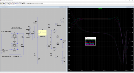
I'm interested in an M2-style amp with more gain to avoid having to use a separate gain stage. Scott's proposed solution looks good, and gives about 21dB gain with the same inexpensive Edcor.
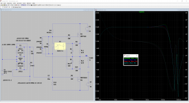
The extra drive requirement of the high-gain arrangement seems to present a special challenge. The input impedance in the high-gain orientation drops to around 40 Ohm near 20 kHz (see 1st picture). The Norwoods will likely be needed. With the Norwoods, however, come a decreased output impedance of the buffer stage. This complicates matters, since the Edcor's 20kHz peak is naturally suppressed in the original design both by the RC damper (using Jensen's language) and the relatively high output impedance of the original buffer.
While the the audibility of the Norwood's impact to the 20kHz peak has been questioned before, the output impedance of the input buffer can make a substantial difference in simulation (see 2nd picture).
If the Norwood's lower output impedance brings the peak back, that can be adjusted with the RC damper (which appears more sensitive to the capacitance) (see 3rd picture).
None of this is new - see here and here for some great data on the Edcor. This data is consistent with the general trends observed in the simulations, but it actually looks better than simulated.
I don't have any experience with these circuits in the real world. What sort of downsides am I looking at when I increase the C in the RC? The bandwidth drops some with the earlier roll-off. While I can (probably) measure AC frequency response with a multimeter and sinusoidal .wav files, is there any practical way to select C without a scope and function generator to check the square wave response?
Surprisingly both 15dB and 21dB auto-transformer modes match sim vs measurement fairly well, with the biggest difference being less peaking at 20kHz or so. An appropriate R/C damping network could probably make both very flat at the top end.
The extra drive requirement of the high-gain arrangement seems to present a special challenge. The input impedance in the high-gain orientation drops to around 40 Ohm near 20 kHz (see 1st picture). The Norwoods will likely be needed. With the Norwoods, however, come a decreased output impedance of the buffer stage. This complicates matters, since the Edcor's 20kHz peak is naturally suppressed in the original design both by the RC damper (using Jensen's language) and the relatively high output impedance of the original buffer.
While the the audibility of the Norwood's impact to the 20kHz peak has been questioned before, the output impedance of the input buffer can make a substantial difference in simulation (see 2nd picture).
If the Norwood's lower output impedance brings the peak back, that can be adjusted with the RC damper (which appears more sensitive to the capacitance) (see 3rd picture).
None of this is new - see here and here for some great data on the Edcor. This data is consistent with the general trends observed in the simulations, but it actually looks better than simulated.
I don't have any experience with these circuits in the real world. What sort of downsides am I looking at when I increase the C in the RC? The bandwidth drops some with the earlier roll-off. While I can (probably) measure AC frequency response with a multimeter and sinusoidal .wav files, is there any practical way to select C without a scope and function generator to check the square wave response?
Attachments

Maybe your best bet is to create a new input stage daughter card, specially designed to have exactly the output impedance you feel is optimum for driving the Edcor in 21dB configuration. However you will need a function generator and oscilloscope to test the daughter card and verify its performance. One of the test fixtures I built is shown in post #439 of this thread, but there are plenty of ways to skin that particular cat.
I think it's worth remembering that just because Jensen Transformers suggests choosing the component values for the transformer Zobel network by tweaking the time domain response, doesn't mean you have to do it that way too. Maybe you'll be thrilled with your results when tweaking the network and tailoring the frequency response instead. Who knows? I admit that I myself don't know; I haven't fooled around with any transformer options except the Official M2 schematic drawn by Nelson Pass. Nor have I experimented with any Zobel component values other than the ones NP used.
I think it's worth remembering that just because Jensen Transformers suggests choosing the component values for the transformer Zobel network by tweaking the time domain response, doesn't mean you have to do it that way too. Maybe you'll be thrilled with your results when tweaking the network and tailoring the frequency response instead. Who knows? I admit that I myself don't know; I haven't fooled around with any transformer options except the Official M2 schematic drawn by Nelson Pass. Nor have I experimented with any Zobel component values other than the ones NP used.
- Home
- Amplifiers
- Pass Labs
- The diyAudio First Watt M2x