Great look, love the bare alloy and wood face. The best thing about mono blocks are 2 foot long speaker cables.
PF - Holy cow, man!!!! Spectacular. Thanks so much for the stellar pictures and the great information.
Wait... DANG YOU! Now I have to try the HP trick and fiddle around. 😀
Wait... DANG YOU! Now I have to try the HP trick and fiddle around. 😀
Thanks for the props guys!
"Breathing" LED? How? Was thinking RED for some reason...
?? --> How to Make an Led Pulse Circuit : 3 Steps - Instructables
??? --> Building the TARDIS - (Pulsating LED Circuit) : 11 Steps (with Pictures) - Instructables
@6L6, I realize the bias is auto—you said check it—which taught me ohm's law—again. ;-)
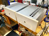
Spectacular build! The monobloc chassis look gefrigginge awesome with a heatsink on only one side and with asymmetric vent holes. I'm sure the "antique white wood" faceplates will be killer gorgeous too. Give some thought to pairing them with a blue LED that rhythmically "breathes" -- drop dead awesome.
"Breathing" LED? How? Was thinking RED for some reason...
?? --> How to Make an Led Pulse Circuit : 3 Steps - Instructables
??? --> Building the TARDIS - (Pulsating LED Circuit) : 11 Steps (with Pictures) - Instructables
@6L6, I realize the bias is auto—you said check it—which taught me ohm's law—again. ;-)
Last edited:
Nice Job P! Wait till you get in in the main system. 🙂
Thanks! Yes... Can't wait!
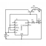
Here's the heart throb LED schematic Mark Johnson. Will have to drop the voltage since I have like 24.5 on the rails and it looks like the timer won't like that... but I could make a couple of these! Already learned a bit about voltage dropping with an Iron Pre add on.
?
Attachments
PF - can I add my Wow! Gorgeous! to the rest? Labour of love!
I completed one a few months back and a good friend appropriated it and promptly talked me into building one for him. Lockdown arrived before all the bits and every time I ask if I can get my amp back I’m told ‘Remember, if you break curfew I’m a Supreme Court judge!!’ He is. Enjoy them, I miss mine.
I completed one a few months back and a good friend appropriated it and promptly talked me into building one for him. Lockdown arrived before all the bits and every time I ask if I can get my amp back I’m told ‘Remember, if you break curfew I’m a Supreme Court judge!!’ He is. Enjoy them, I miss mine.
PF - can I add my Wow! Gorgeous! to the rest? Labour of love!.
Thanks! It's true—labor of love.
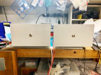
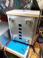
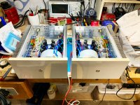
So here's how the fronts happened in the end—ditched the old wood thing—wasn't right for this...multiply is a good transition from aluminum. I'll put them in the main system tomorrow—with Ishikawa—so I can get a sense of NP original intent before messing about.
I'm pretty happy with how they came out—lot of work though..... VERY solid. I tried a red LED and it completely got lost visually on the white...So white it is...
(I have all the parts to make a throbbing LED)
Man this is an awesome amp. What a privilege to have these incredible designs available and this incredible forum!
Attachments
Last edited:
Thanks! It's true—labor of love.
So here's how the fronts happened in the end—ditched the old wood thing—wasn't right for this...multiply is a good transition from aluminum. I'll put them in the main system tomorrow—with Ishikawa—so I can get a sense of NP original intent before messing about.
I'm pretty happy with how they came out—lot of work though..... VERY solid. I tried a red LED and it completely got lost visually on the white...So white it is...
(I have all the parts to make a throbbing LED)
Man this is an awesome amp. What a privilege to have these incredible designs available and this incredible forum!
Well done! That is one impressive build!

Thanks for the props guys!
Those cabinets look gorgeous 🙂
Can you please provide the dimensions of the cabinet including the heat sink fins as I am also planning for the same for my USSA-5 amp.
Thanks
Those cabinets look gorgeous 🙂
Can you please provide the dimensions of the cabinet including the heat sink fins as I am also planning for the same for my USSA-5 amp.
Thanks
Thanks!
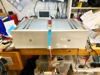
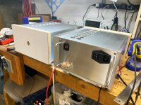
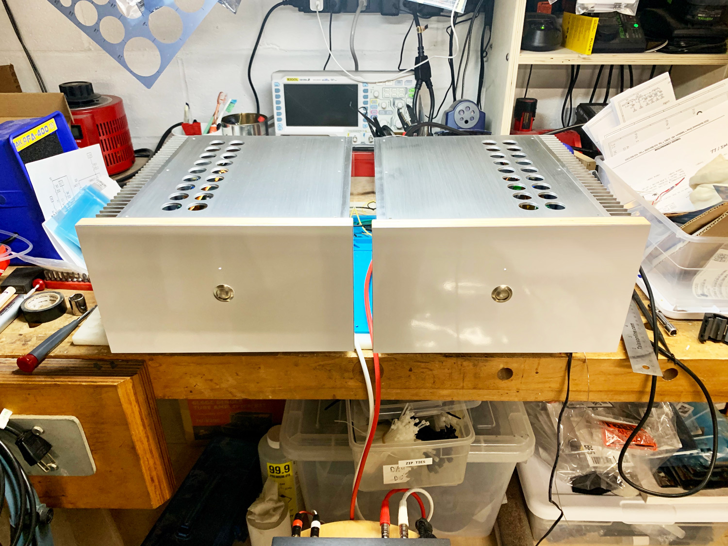
10.75"W x 12"D x 6"H Overall dimensions not including ply front or D handles.
Or basically based off the heatsink dimensions (heatsinkusa.com) which are 1.3125" x 12" x 6". They barely get warm, probably could have gone with a shorter extrusion, say 5" and sourced a smaller 200VA donut. But I think the front proportions are nice.
The baseplate is .25" aluminum and is 9" x 12". The panels opposite the heatsinks are .375" thick. All other other plates are .125" thick. 6061 aluminum, though recently I used some 5052 aluminum for the Cordell gain clone amp and it seems to finish easier? The alloys are very similar though....
sendcutsend.com (if in USA, not sure about INTL shipments) will cut anything from a file up to .5" thick in 5052 in single pieces for really great pricing all things considered, quality is excellent and they are very friendly. I may use them next time since it would save time and be really really precise—I'm precise, but...not a computer.
I'm not sure I will ever buy a chassis again to be honest. Way more rewarding overall. I think I'd rather find some anodizing resources... so black is an option...
Last edited:
sendcutsend.com (if in USA, not sure about INTL shipments) will cut anything from a file up to .5" thick in 5052 in single pieces for really great pricing all things considered, quality is excellent and they are very friendly. I may use them next time since it would save time and be really really precise—I'm precise, but...not a computer.
Incredible work on your build. Thanks especially for this recommendation - I hadn't realized prices were this reasonable.
Incredible work on your build. Thanks especially for this recommendation - I hadn't realized prices were this reasonable.
Thanks! And yes... Totally new age—and those guys really are great—I've tried a few different places. Check out Ponoko.com. They are very good too for thin materials (max 3mm at this time), but have more than metal—more $$ though—and their prices just went up.
My friend currently has an M2x in a 5u chassis i built for him but I want to help him change it to dual mono. I have the spare power supply board coming in and the 2nd AS-4218 transformer.
How do I wire the safety caps, thermistors, and transformers together in one chassis? Does anyone have pics I can reference or a drawing to help me wire it correctly?
I’ve heard this amp sounds so much better in dual mono or as monoblocks.
How do I wire the safety caps, thermistors, and transformers together in one chassis? Does anyone have pics I can reference or a drawing to help me wire it correctly?
I’ve heard this amp sounds so much better in dual mono or as monoblocks.
Dual mono chassis - double everything except for the mains socket*, mains switch and switch snubbing capacitor.
* Usually contains the mains fuse, if it doesn't, you have the opportunity to use one per transformer.
* Usually contains the mains fuse, if it doesn't, you have the opportunity to use one per transformer.
A dual mono build should really have independent line fuses for each channel. That provides better protection and makes it easy to test one channel at a time.a
After the fuse, each PSU should look like the complete one you would have built to share between both channels. Each channel should have its own ground loop breaker between audio ground and chassis. This may be built with a single 25A bridge rectifier and a pair of 10 Ohm resistors.
After the fuse, each PSU should look like the complete one you would have built to share between both channels. Each channel should have its own ground loop breaker between audio ground and chassis. This may be built with a single 25A bridge rectifier and a pair of 10 Ohm resistors.
Thanks for the help. So, I will build each side the same as I would for one amp but add in a fuse for each transformer primary wire. A couple questions:
- Should I just increase the two fuses in the IEC at the switch?
- For the individual fuses, should I keep them at 2.5A slow blow?
- For C3, can I lower the Voltage from 3300uf/50V to 3300uf/35V? I have some spare parts left over from some Amp Camp upgrades.
Thanks.
- Should I just increase the two fuses in the IEC at the switch?
- For the individual fuses, should I keep them at 2.5A slow blow?
- For C3, can I lower the Voltage from 3300uf/50V to 3300uf/35V? I have some spare parts left over from some Amp Camp upgrades.
Thanks.
It could be lower depending on the rails, but 6 is right, I never want to run a part near it's limits when one with room to spare is not cost prohibitive.
- Home
- Amplifiers
- Pass Labs
- The diyAudio First Watt M2x