Posts #105 and #106 discuss this. Look for the expression
I certainly don't mind spending your money
I certainly don't mind spending your money
Posts #105 and #106 discuss this. Look for the expression
I certainly don't mind spending your money
Mark, we are, "audiophiles," which means a $800 cable has to be better than some helical DIY for $80.🙄
.. and that’s why I used a decent cap rated at 35V, bypassed with a surplus 1 uF polypropylene cap.
.. and that’s why I used a decent cap rated at 35V, bypassed with a surplus 1 uF polypropylene cap.
You go Wilma! Never could espell. 😉
mains fuse blows once and a while
..
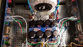
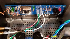
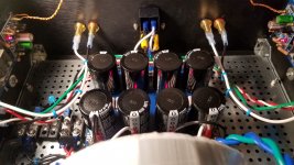
Hi everyone! I finished my build, well almost. I can't celebrate yet.I have 2 problems I need help with. One is with the fuses blowing in the IEC. They only blow after switching on and not always. Three sets so far. Is it the Safety capacitor at the terminal block? The amp has been on for 2 hours or more, no problem. Only switching on and not every time. The first time it blew I switched on and off within 10 seconds. I started to wait a few minutes in between switching on and off and that worked, for a while. Is the safety capacitor at the terminal block the problem? I'm going to town for more fuses. I'll be back in 4 hours.
My other problem is the trimmer RV1.Channel B I can adjust the DC output to zero. Channel A I can only get down to 34mv.
When someone has time can you please help?
..
Hi everyone! I finished my build, well almost. I can't celebrate yet.I have 2 problems I need help with. One is with the fuses blowing in the IEC. They only blow after switching on and not always. Three sets so far. Is it the Safety capacitor at the terminal block? The amp has been on for 2 hours or more, no problem. Only switching on and not every time. The first time it blew I switched on and off within 10 seconds. I started to wait a few minutes in between switching on and off and that worked, for a while. Is the safety capacitor at the terminal block the problem? I'm going to town for more fuses. I'll be back in 4 hours.
My other problem is the trimmer RV1.Channel B I can adjust the DC output to zero. Channel A I can only get down to 34mv.
When someone has time can you please help?
Last edited by a moderator:
Can't load the images you have here, and what size fuse is it? Is the offset pos or Neg?
See this from one of Mark's posts:
3. WARNING: BLASPHEMOUS HERESY! DO NOT READ THIS! Some DIY builders of the M2 amplifier, using the very fine “Tea‐Bag” circuit board, have reported a problem to the diyAudio forums. Their M2 amplifier’s output offset voltage is negative, and no setting of trimmer resistor RV1 removes this negative offset. I would like to gently mention a possible fix: leave R7=47K, but change R6 to 37K and change RV1 to 20K. Now (R6+RV1) can vary from 37K to 57K, in other words, from (10K less than R7) to (10K more than R7). This lets you null out either polarity of offset voltage. However, to faithfully reproduce Nelson Pass’s original M2 design, the M2X schematic and PCB silkscreen do not include this modification. M2X has R6=47K and RV1=5K. If you decide to make this R6,RV1 modification on your M2X, don’t tell anyone. And don’t quote me.
(Editor's note - (Jim) In my experience with all these Pass projects, I've found that Papa's coffee cans full of parts are really well sorted and all seem to be "center of tolerance " parts. This means that when we buy parts in low quantities we end up with parts that are further along the curve, so to speak... and need to have a bit more adjustment around them to set biases and null offsets and the like. The BA-3 Complimentary has needed this as well as the Tea-Bag M2 board, and the M2x. Anyway, my point is to agree with Mark and strongly suggest making the changes to that resistor and pot; all it does is give more adjustment to center the operating points, and because we can use our parts and properly adjust the circuit, it will sound better. 😀 )
Are you using the forum tools to upload images? Best route... The last post isn't working either...
I don't ever subscribe to blasphemous heresy—unless it works perfectly. ;-)
I don't ever subscribe to blasphemous heresy—unless it works perfectly. ;-)
The pictures I tried the paste url in the first time. The second time I resized and dragged to dialog box. I'll get it.
Both blow. the size is 2amp 250 v.
Yeah I tried resizing the pixs with no luck
Nelson calls for 2.5A slow blow...
http://www.firstwatt.com/pdf/prod_m2_man.pdf


What color is the hot wire coming from your IEC? If it's white, your inrush looks okay to me.
Last edited:
I deleted the weird uploads in the posts where the photos didn't show.
Fuse - If the thermistors are hot, they don't protect from inrush. If you were doing something with the amp and it was on for a while, and you turned it off, and then back on again within few minutes, the fuse will likely blow.
Offset - 34mV is really good and not anything to worry about. If you want to change it so you have enough adjustment range, Thompsontechs quoted the right thing in his post above, the "blasphemous heresy" thing.
Thanks 6L6 I got it now. I'm gonna hook up my Korg and try some music in a few minutes.
Thank you too Thompsontechs I couldn't get 2.5 amp. I got 3 amp.
Thank you too Thompsontechs I couldn't get 2.5 amp. I got 3 amp.
- Home
- Amplifiers
- Pass Labs
- The diyAudio First Watt M2x