Any tips on where to start looking if I’m seeing signs of oscillation on the DC offset? Even after an hour, the offset is swinging all over the place (I can get it to zero, but it will not stay there). Seems like over the course of an hour it will swing about 100mv total in both directions, and it will continually swing up and back down again. Everything else looks fine. Bias appears okay (~.62v at the output resistors). The PSU has properly biased two prior FirstWatt builds (F5 and F6) and voltages look good on both boards and both rails.
Only deviations from the BOM are a 2.2uF in the bypass and an IRFP9140 as the P-Channel mosfet. Installed RV1 as 20K and R6 as 37.4K and confirmed with multimeter that these were in series. No problem adjusting offset with RV1 when it’s powered up. I have tried with two stuffed daughter boards with pretty much identical result as far as DC offset drift goes. Also placed a 8R load on the output and no change in behavior. Inputs are shorted.
Thanks!
Last edited:
![20200410_134115[1].jpg](/community/data/attachments/760/760086-9567ae9e1cb6c7672b714d7fceeb78b3.jpg?hash=lWeunhy2x2)
![20200410_134133[1].jpg](/community/data/attachments/760/760118-87954c95d589c71494175e2a7b494b5d.jpg?hash=h5VMldWJxx)
Pass DIY Addict
Joined 2000
Paid Member
Ah ha!! There is your sleeper 😴
Looks real cool JT!
It’s like my 450HP Caprice rolling on stock 15” wheels and hubcaps 😀
Looks real cool JT!
It’s like my 450HP Caprice rolling on stock 15” wheels and hubcaps 😀
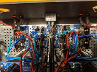
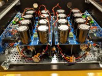
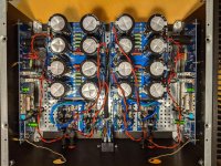
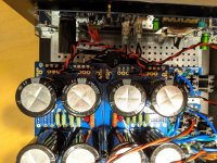
Found in the rubbish bin....
I looked and thought, maybe I can do something here...
Not finished, but..... 😉
How cool is that....?
JT
damn Fugly!!
🙂
I'm up to attic, in a middle of the night!
How cool is that....?
That is the epitome of cool...! 😀
Plus, it makes swapping IPS boards a breeze, I'd bet.

Is the top factory hinged as shown in picture?
You need to have top open during playback to get the heat away?
You need to have top open during playback to get the heat away?
Is the top factory hinged as shown in picture?
You need to have top open during playback to get the heat away?
Yes, it's afactory hinge as it was a record player too. For now, ya, you would have to have it open, but if I want to install a couple fans where the speakers were R & L side, I could run it closed.
Also, the factory on/off knob has been checked out and put in working order, to turn it on you turn the middle knob and that also lights the dial. (This model wasn't lit)
My thought is to finish the wiring and test the unit extensively on the lab bench, if it gets to where I trust and like it, I will install fans to allow it to run with the top down. ( ISHIKAWA Vewrsion BTW)
Last edited:
@ Eric, nope not to UL spec lol.
@ Vunce, ya that was my thought, I built a lot of cars and raced for many years. The stuff I drove on the street didn't look like much, but when you opened the bonnet. 🙂 Of course anyone could here the cam and blower an know there was something going on. lmao
@Zen two Fuglys in as many builds, and sent him to the attic... Score! 🙂
@MyHead Yes, they are ISHIKAWA right now, but swapping boards will be easy.
Last edited:
JT - You hare hereby awarded a gajillion internet points for killer repurposing and recycling. Absolutely fantastic!!!! 
🙂 🙂 🙂
🙂 🙂 🙂
How cool is that....?
That is where it's at, man. You can't buy that kind of cool, you have to make it to own it. The reason for DIY, see.
JT - You hare hereby awarded a gajillion internet points for killer repurposing and recycling. Absolutely fantastic!!!!
🙂 🙂 🙂
Thanks 6, if it wasn't for your, "illustrated build guides," I would have never had the confidence to start down this amazing road.
A big thanks to all who help and continue to help us new people gain the confidence to take on these projects. If it wasn't for you all here many of us would have never had the courage to get started.
My first build: M2X with Ishikawa
Hi all,
After reading through all the good messages on this thread, I have just completed by first amplifier build with M2X + Ishikawa !!
Unfortunately, it does not seem to work 😕 The M2X does not seem to be amplifying the signals.
The PSU seems fine. Tested it separately before amp board is connected. No fuses blown.
The one thing that I would like to check is the amp board test on "Noob's First First Watt" thread. It says:
Check with diode test on DMM – Should show NO voltage.
o (+) Lead to V+ and (-) Lead to output
o (-) Lead to V- and (+) Lead to output
I did the test on the amp board without the Ishikawa daughterboard, it is fine. No voltage shown.
However, with the Ishikawa daugtherboard attached, I got voltages of 0.77v and 0.53v respectively. Is this the problem? What's the best way to test the Ishikawa?
Any suggestions on how to debug the amp?
Attached are some photos of the build of the fun so far 🙂
Attachments
Oh my, first thing that hit me was the soudstage, this things is wide and deep, I'm hearing stuff from behind me lmao. Nice job Mark and Pappa. It doesn't control the bottom end like the AN, but man, this thing is just musical as hell. Dire Straits playing right now WOW!!
@delboy,
You should be seeing close to rail voltage on the daughter card two will read almost rail and two ground.
Unplug from the amp board from the supply and check the supply alone, what are your rail voltages? Plug the supply back into the amp and check the rails again at the power supply. For instance I get + - 30volts unloaded and about +- 27-28V plugged into the board. When I test the standoffs to the daughter (Ishikawa) I get slightly less than the rail.
If your rail voltages look okay, then it's time to break out the schematic and go back through everything. Also, I always fire up one side at a time. That way if you hosed something, you don't smoke everything.
If the rail voltages are still good, let us know what you have on the legs of Q1 and Q2
Here are some number off mine to help ya out.
Q1
Gate 5.16V
Drain=Rail or in my case about 28V
Source 738mV
Q2 should be very close to what Q1 is only Neg instead of Pos
Last edited:
Oh my, first thing that hit me was the soudstage, this things is wide and deep, I'm hearing stuff from behind me lmao. Nice job Mark and Pappa. It doesn't control the bottom end like the AN, but man, this thing is just musical as hell. Dire Straits playing right now WOW!!
You have built a proper dual-mono power supply. That's where the amazing soundstage comes from. 🙂
You may assist the control of the bottom end by adding 12,000 uF to 24,000 uF to the outputs of the SLB boards. Ripple eaters do just that; energy storage comes from real capacitance.
@delboy123 - FWIW the method I "borrowed" and put in that thread (I believe it was attributed to TungstenAudio if memory serves) is for testing the boards with the power off - no PSU connected - no amp powered up. Just bare boards on heatsinks to check for shorts etc.
It may be obvious, but the others are quoting voltages with the amp under power.
@Thomsontechs - IMHO Pass amps are made for Dire Straits. It is uncanny how some of the amps create not just a soundstage, but an entire environment. Enjoy!
It may be obvious, but the others are quoting voltages with the amp under power.
@Thomsontechs - IMHO Pass amps are made for Dire Straits. It is uncanny how some of the amps create not just a soundstage, but an entire environment. Enjoy!
You have built a proper dual-mono power supply. That's where the amazing soundstage comes from. 🙂
You may assist the control of the bottom end by adding 12,000 uF to 24,000 uF to the outputs of the SLB boards. Ripple eaters do just that; energy storage comes from real capacitance.
Hello TA, thanks for the input, I have 15,000uF x 4 in each SLB, one SLB for each channel, do you think that number should be increased?
JT
- Home
- Amplifiers
- Pass Labs
- The diyAudio First Watt M2x