The problem is: your ohmmeter is measuring the impedance of the enormous filter capacitors in the power supply. Since that impedance is incredibly low your ohmmeter incorrectly says there is a short.
Try it with a few electrolytic capacitors you have lying around on your bench. Observe how the ohmmeter reacts as you increase or decrease the capacitance you ask it to measure.
Try it with a few electrolytic capacitors you have lying around on your bench. Observe how the ohmmeter reacts as you increase or decrease the capacitance you ask it to measure.
I admit I'm struggling with the word "problem". Let's please separate this out into "probably functioning as intended" or "probably not functioning as intended". I've taken the power supply out to look for physical issues that could contribute to shorts and have come up with nothing. I've spent two hours on it.
As I said previously, I measured everything per the build guide and saw no issues. I further stated that the power supply was producing proper voltages. Now, I feel like I'm chasing my tail trying to diagnose a "problem" that is within the normal operating characteristics of the power supply per a measurement you've suggested. You introduced the word "problem". I'll own not asking what you meant by "problem".
I'm always willing to learn, but if I've now taken literally everything apart to look for a characteristic you've described as a problem, that is not a problem - I'll take this as a learning and move on. I want my amp back together.
Please clarify.
Rail fuses is a good thing if you have a short it will blow. Also a vario-transformer is good so you can slowly turn up the main voltage and check the current if it raises unexpected and/or a good lab-supply with current limiter. I have it all and have until now only burned a couple of fuses in a case where it could not handle the in-rush current in a smaller PSU with no in-rush limiter. A vario-trafo is rather cheap and I think it is a "must" to have as "DIY person" 🙂
Hi @MEPER - Thank you very much. Always appreciated.
From what I've gathered, there is no "short" in the PSU. Per Mark's explanation, a bit of schematic review, and a bit more reading, I now understand that there is no "problem" with the PSU. I misunderstood his original intention, I believe, as he was trying to teach this old dog a new trick. At least I hope 😀
I went back through my build notes and ran the sequential checks I used before powering up for the first time. No issues were revealed in the PSU or the amp boards. I have all of the gear you've mentioned. In addition, I used the simple dim-bulb tester first on the PSU. Then I ran through all the checks, and put it all back together using the original Keratherm just to tempt fate. I allowed it to sit over night, and checked / tweaked the DC offset again this morning. DC offset is below my DMM's operating range, and AC noise is still below my DMM's operating range. After all the checks and re-checks, I felt pretty good hooking it up. It's making beautiful music again on the test bench with the new C2 caps and the Austin boards installed.
I think everything in the overall amp is per normal, even if there are few measurements I still don't quite understand. I can live with that for now. I continue to learn.
Whatever the "problem" might be or may have been, I can't imagine that it was Keratherm. My best guess is that the real problem is my lack of understanding re: the circuit's operation.
If there actually is a wiring or other assembly error, oh well. I'll continue to listen to beautiful music until it reveals itself through a symptom in operation and go from there. It's got 100s of hours on it already, and I'm sure I'll get 1000s more.
As always thanks to Mark, @TungstenAudio, and all the rest of the community for jumping in to help and teach.
The issue is: your ohmmeter does not give correct readings when enormous power supply capacitors are connected between its probes.
The solution is: when trying to find out whether or not an M2X output transistor's pins are shorted to the heatsink, disconnect the power supply wires (Vpos, Vneg) before making the measurement.
Ten minutes ago, I connected my multimeter(s) to my M2X power supply. One of them was a fairly high-end model: the Brymen 869S. The other meter was a 25 year old, cheap Chinese rebranded model (3 digits, no autoranging, no backlight), like the ones Harbor Freight sells for $9.99.
With the meter set to measure resistance, I connected its probes to Vpos and GND. The digital readout said 50 ohms and the number kept growing. After 15 seconds the "resistance" read 450 ohms and it continued to rise. The readings were about the same on the fancy expensive meter and on the old decrepit cheap meter. Starts low and rises, gets to ~450 ohms after 15 seconds.
What's happening is: the ohmmeter forces out a known constant current "I" and measures the resulting voltage "V". Then by Ohm's Law, resistance = (V/I). With a capacitor connected to the probes, the current I charges the capacitor, and the voltage slowly ramps up according to the good old capacitor equation dV/dt = I/C. Unfortunately, the meter keeps re-calculating Ohm's Law, once or twice per second, and it displays the ratio R=(V/I), which keeps growing as V rises.
I am a little surprised that your ohmmeter doesn't behave the same way. It seems that your ohmmeter does not charge up the filter capacitors inside the PSU, so your "ohms" reading does not climb up to 450 ohms and beyond, if you patiently watch it for 15 seconds. Honestly, it it were me, I would switch to a different multimeter, and if necessary I would hop on Amazon.com and buy a new meter for $35. But even with the new meter, check for shorted output transistors ONLY with the supplies disconnected.
Hi Mark -
Thank you as always. I'm honored that you take the time and have the patience to explain things so clearly. I believe that is what I experienced and obviously poorly described in post #2436 saying...
" measuring the resistance between the V- and Ground wires from the PSU for the right channel. It started out at ~150 ohms then climbed to over limit. I thought something was weird with the DMM. I went to grab another meter and got 0 Ohms. I went back to step #3 and it did the same thing with the other meter. It repeated. If I move between measurement points quickly enough, it reads roughly the same (high) resistance. If I wait long enough, they go back to 0. I don't know the circuit as well as I should, but it acts like it's charging the caps. If I leave the test leads in place long enough, they'll all go to over limit."
I've learned quite a bit with your help over time. The amp has been back in the main system now for a few hours, and I'm loving the Austin board (again).
Oops I missed that quote completely. It does reinforce the idea: disconnect the supply(s) before performing continuity checks. Glad you were able to put everything back together again and let it continue with its task: producing beautiful sound!
Oops I missed that quote completely. It does reinforce the idea: disconnect the supply(s) before performing continuity checks. Glad you were able to put everything back together again and let it continue with its task: producing beautiful sound!
Not a worry - I always learn. I asked earlier (in the very first post re: the experience) and subsequently in follow up posts if the readings for shorts should be done with or without the PSU and output connected. I worded it poorly. I'll work on being more concise, repeating all critical elements within one post, requesting and confirming clear YES/NO answers before moving forward, and keeping the edits to an absolute minimum.
Continuing in the positive column - I now know I can tear down an amp and get it swapped to other boards for subsequent FW builds using the same PSU and chassis in under two hours with all pre-music checks done properly. 😀 Now I just need to get the parts ordered and get them built.
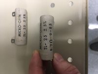
RV1
Not sure if this has come up before but RV1 in the amp board BOM is specified as a TT 64WR5KLF. W-series has offset pins. Y-series has straight line pins. The BOM correctly describes it as "three pins in straight line" but just blindly ordering the part number gets you the wrong part. I know, I did just that.
The correct part number would be 64YR5KLF (or 64YR20KLF if doing the modified version of the circuit).
... The BOM correctly describes it as "three pins in straight line" but just blindly ordering the part number gets you the wrong part. I know, I did just that.
The correct part number would be 64YR5KLF (or 64YR20KLF if doing the modified version of the circuit).
I agree, the part# field of the BOM is wrong but the description is correct. Thank you for pointing it out! I will find out what we need to do to make the correction, and to get the updated BOM loaded here.
Greetings to all fellow M2x builders.  I have started this excellent project as well.
I have finished stuffing one channel of the PCBs and I tried to measure the DC offset of my Ishikawa input board, since I don’t want to install the C1 capacitor. So I left one corner without the standoff and nut (see the attached photo) and fed the board with a lab supply +-24V. Then I measured the Ishikawa output with input shorted and saw only ~2mV.
Is this a proper way to measure the input board’s DC offset?
I have started this excellent project as well.I have finished stuffing one channel of the PCBs and I tried to measure the DC offset of my Ishikawa input board, since I don’t want to install the C1 capacitor. So I left one corner without the standoff and nut (see the attached photo) and fed the board with a lab supply +-24V. Then I measured the Ishikawa output with input shorted and saw only ~2mV.
Is this a proper way to measure the input board’s DC offset?
Attachments


Yes that setup in #2454 will work well for measuring output offset voltage. Be sure to check the voltages on all four pins.
Input: should be zero volts
Pos Supply: should be +24V or whatever your power supply provides
Output: (measure offset voltage here)
Neg Supply: should be -24V or whatever your power supply provides
You're double checking that the other three I/Os make good connection to the circuit nodes they're supposed to.
Just finished my M2x. Loaded some Tucson boards, let 'er cook awhile until stable and zeroed out the DC on the loudspeaker terminals. Initial impression, very favorable, and it's not even burned in yet. The auto-biased outputs are running cooler than my F6, at around 45 - 47 deg C. I had to bias the F6 at 1.6 A (almost 60 deg C) to get it to sound good. Could not stand to listen to the F6 at the initial build guide 1.05 amp bias. The Tucson/M2 sounds a bit cleaner and more forward than the F6, not quite as laid back. Burn in may change that. Now I'm looking forward to comparing the sound of the other M2 input modules to my reference F6.
Side note: I was re using some 4RU 300X165 diyStore heat sinks from another build and wanted to limit the number of new holes to drill and tap so my M2 boards ended up offset to one end of the heat sinks. This is about an inch off center, horizontally. Interestingly enough, that makes a measurable difference in the mosfet case temperatures. 47.8 deg C for the devices 1" off center and closer to the edge, 45.0 deg C for the devices with more heat sink available horizontally. So layout is critical, even on the big heat sinks.
FYI, the power button is a 22mm latching push button w/ blue LED ring, where the ring moves with the button. Much nicer than the 19mm by the same manufacturer, where the ring is fixed, making the button effectively even smaller. Well worth the extra $3.60. I used an extra 15K ohms external to the LED to add to the internal resistor rated for 12VDC supply. A casual look at the specs make it seem this switch only has 12V rated contacts but the expanded specs show 250V/5A. A 10A rated version is available for a few dollars more.
Amazon.com: API-ELE [3 year warranty] 22mm Latching Push button Switch 12V Angel Eye Ring Light LED Waterproof Stainless Steel Round Metal Self-locking 7/8'' 1NO 1NC (Blue): Automotive
Attachments
Congratulations on a lovely build! The front panel looks stark and imposing.
It's hard to see in the photos, do you mount the rectifier diodes to the perforated floor plate? If so, does it provide enough heat sinking that the diodes run acceptably cool?
It's hard to see in the photos, do you mount the rectifier diodes to the perforated floor plate? If so, does it provide enough heat sinking that the diodes run acceptably cool?
That is a good looking build! I like the 22mm illuminated power switch, and the fact that it's rated for 250VAC as well as 12VDC. Thanks for the lead.
I used a smaller chassis for my M2x, about 2.5U tall and 400mm deep. I wanted to place the Edcor transformers as far away as possible from the big power transformer, so the boards are not centered on the heat sinks. Yes, the rear of my amp runs noticeably warmer than the front, but bias and offset are stable, and it sounds wonderful. I also used IRFP9140s for the P-type to get a closer match to the transconductance of the IRFP240s, so letting the 240s run a little warmer may just add a little H2 warmth to the sound.
I used a smaller chassis for my M2x, about 2.5U tall and 400mm deep. I wanted to place the Edcor transformers as far away as possible from the big power transformer, so the boards are not centered on the heat sinks. Yes, the rear of my amp runs noticeably warmer than the front, but bias and offset are stable, and it sounds wonderful. I also used IRFP9140s for the P-type to get a closer match to the transconductance of the IRFP240s, so letting the 240s run a little warmer may just add a little H2 warmth to the sound.
Congratulations on a lovely build! The front panel looks stark and imposing.
It's hard to see in the photos, do you mount the rectifier diodes to the perforated floor plate? If so, does it provide enough heat sinking that the diodes run acceptably cool?
Mark
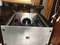
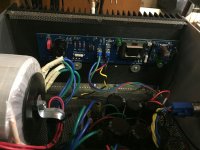
Power supply is built on old school 1/8" fiberglass G10 board with staked hollow turrets. The board is up on standoffs. That allows wiring between the turrets above and below the board, like a double sided PCB. Wire wrapped and soldered to the filter cap snap-in terminal lugs on the board underside keeps the caps tight to the board on the top side.
The 35A bridge rectifiers are mounted at one end of the board with a full width piece of 1-1/4" X 1-1/4" aluminum angle sandwiched between them and the board for heat sinking. I have not measured temp under load but will do that, report and send a better pic.
Total investment in the empty chassis is under $100 including the $70 heat sinks. It consists of a 0.125" plate aluminum front, a 0.063" plate aluminum rear and some 20ga perforated steel sheet metal. Aluminum is cut on a standard table saw with a carbide blade by clamping the aluminum between two pieces of plywood and being very careful (kids - don't try this one at home). Perf metal top/bottom support "angle irons" are made by clamping the perf edge between two pieces of wood and bending 90 degrees. Perf metal cuts with tin snips. Feet (not seen) are from my 3D printer. The heat sinks are strong enough to hold everything together with the front and rear panels bolted on tight. Front panel was "brushed" with a belt sander. Have done a better job with that in the past.
- Home
- Amplifiers
- Pass Labs
- The diyAudio First Watt M2x