The drain legs of the Mosfets are supposed to be electrically isolated from the heatsink.
The Keratherm pads are, unfortunately, best as just single use items. You can see that you have been lucky with some of your transistors, but not all. Your best bet is to replace the Keratherm pads with new ones, or maybe switch to a different material.
You might get lucky by using a smooth, flat whetstone to burnish the mounting locations of the Mosfets, and trying the old pads one more time, but it's a long shot. You were smart to do the continuity checks that you did. A while back I switched to using ceramic pads for this very reason.
The drain legs of the Mosfets are supposed to be electrically isolated from the heatsink.
The Keratherm pads are, unfortunately, best as just single use items. You can see that you have been lucky with some of your transistors, but not all. Your best bet is to replace the Keratherm pads with new ones, or maybe switch to a different material.
You might get lucky by using a smooth, flat whetstone to burnish the mounting locations of the Mosfets, and trying the old pads one more time, but it's a long shot. You were smart to do the continuity checks that you did. A while back I switched to using ceramic pads for this very reason.
Thanks so much as always for your help. See my edits if you have a second, please. Does this hold true with the PSU and Output wires attached?
It seems odd, but I continue to learn. Fortunately, I have a ton of Keratherm pads and can easily replace them. I sanded the sinks with an emery board and the whetstones one poster had recommended. I'll touch it up again.
Edited to add - I looked for "ceramic isolation pads" on Mouser and Digi-Key with no luck. Would you happen to have a brand or part description?
Edited to add (yet again - apologies) - when the boards are disconnected from PSU and Output - there are no shorts to sinks / ground on either the right or left channel. What is interesting (to me) is that when the boards are connected with the input boards - the Austin board has continuity through both drains. The Norwood only has continuity through Q2. I really need to improve upon my ability to understand schematics.
Last edited:
Here is an M2x amplifier board removed from the heatsink and turned upside down.
The picture shows the electrically conductive backside tab on each of the power transistors; the IRFP9240 datasheet calls this tab "Pin 4" and tells you that it is internally connected to "Pin 2" which is DRAIN. You can also see that there is quite a large gap between Pin 4 and the hole in the plastic where the mounting bolt passes through. When the bolt is correctly installed, there is no way for the bolt to short to Pin 4.
I suspect that there are one or more regions of the Pin 4 metal tab, which do not have Keratherm insulator below. Either due to misalignment, or due to a pinhole in the Keratherm.
I bet if you connect one end of your ohmmeter to the heatsink (perhaps using the mounting bolt of the other transistor), you'll find that this transistor's drain is shorted to the heatsink even when its mounting bolt is completely removed. Unscrew the bolt, use your thumb to press the transistor down onto the Keratherm, and make the measurement. I bet you'll find that drain is still shorted to heatsink. Which means the bolt is not the problem. Keratherm is the problem. You can verify this by temporarily sliding a 3 inch by 3 inch piece of copier paper between the transistor and the heatsink. Reinstall the bolt (it will easily pierce the paper) and tighten it down. Has the short between drain and heatsink disappeared? I bet it has. Yet the bolt is there. So the bolt is not the problem. Keratherm is the problem.
~
Attachments
A while back I switched to using ceramic pads for this very reason.
As soon as I read how easy it is to damage Keratherm I started looking for these: found them on Aliexpress.com.
Mark Johnson has given a great and very detailed explanation of the issue. The Keratherm pads are good for one use, but rarely more than one. Since you have plenty of extra Keratherm pads, it will be easy to discard the old ones and replace with new ones.
I have switched to these, especially on the amps that I may tinker with:
4180G Aavid | Mouser
I have switched to these, especially on the amps that I may tinker with:
4180G Aavid | Mouser
Mark Johnson has given a great and very detailed explanation of the issue. The Keratherm pads are good for one use, but rarely more than one. Since you have plenty of extra Keratherm pads, it will be easy to discard the old ones and replace with new ones.
I have switched to these, especially on the amps that I may tinker with:
4180G Aavid | Mouser
Thanks for the reference, very useful !
Here is an M2x amplifier board removed from the heatsink and turned upside down.
The picture shows the electrically conductive backside tab on each of the power transistors; the IRFP9240 datasheet calls this tab "Pin 4" and tells you that it is internally connected to "Pin 2" which is DRAIN. You can also see that there is quite a large gap between Pin 4 and the hole in the plastic where the mounting bolt passes through. When the bolt is correctly installed, there is no way for the bolt to short to Pin 4.
I suspect that there are one or more regions of the Pin 4 metal tab, which do not have Keratherm insulator below. Either due to misalignment, or due to a pinhole in the Keratherm.
Excellent explanation. I think I have that understanding down now. Thank you very much!
I bet if you connect one end of your ohmmeter to the heatsink (perhaps using the mounting bolt of the other transistor), you'll find that this transistor's drain is shorted to the heatsink even when its mounting bolt is completely removed.
No. It behaves exactly the same. Argh! I'm so confused. But, note previous question from post 2420. I'm only concerned if this is to hold true when it's connected to V+ V-, their associated grounds and Output. There is no continuity when it's just bolted to the heatsinks. I'm not sure if that got lost in my edits of previous posts and my subsequent question to @Tungsten Audio.
Unscrew the bolt, use your thumb to press the transistor down onto the Keratherm, and make the measurement. I bet you'll find that drain is still shorted to heatsink. Which means the bolt is not the problem. Keratherm is the problem. You can verify this by temporarily sliding a 3 inch by 3 inch piece of copier paper between the transistor and the heatsink. Reinstall the bolt (it will easily pierce the paper) and tighten it down. Has the short between drain and heatsink disappeared? I bet it has. Yet the bolt is there. So the bolt is not the problem. Keratherm is the problem.
~
Summary - the paper behaves exactly the same as the Keratherm (both old and new) and both before and after a fresh emery / hone treatment.
----------
@Mark Johnson and @TungstenAudio -
Thanks to you both for the clear and detailed explanations and your patience.
I'll try to keep this concise in addition to above.
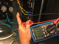
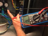
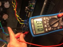
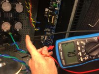
I tried the paper. The paper and the Keratherm (both old and new) behave the same. I've attached a few photos showing just the Q2 check on the right channel with the Norwood board installed. This board was untouched until I swapped the Keratherm and paper.
The Keratherm and paper behave the same. This leads me to believe I've borked something else. I wish I understood the schematic a bit better. Would it help at all for diagnostics if I unplugged each of the V+ / Ground / V- / Ground / Output from the board individually and checked continuity?
Pictures may be more clear than my explanations. I was simply using the bolt as a substitute for the heatsink since it's easier to get good contact. In the pics below, I ensured I had good electrical contact with the sink through a mounting hole and the drain for Q2.
Sadly, they're rotated 90 degrees, but it should be clear.
The first picture shows the behavior with the new Keratherm with all the standard leads attached to the board - continuity. Resistance from drain to heatsink (11 ohms)

The second picture shows the behavior with the same Keratherm with the connections removed. No continuity.

The third picture shows the behavior with the paper with all the standard leads attached to the board - continuity. Resistance from drain to heatsink (11 ohms)

The fourth picture shows the behavior with the paper with the connections removed. No continuity.

As always your guidance is appreciated.
My forum skills are lacking - edited to show pictures.
Last edited:
Remember that the PSU is shared between the left and right channels.
Remember that the Positive DC Supply is connected to the Nchannel MOSFET's drain-- on both boards. So if there's a short from drain to chassis on one of the two boards, it will measure "shorted" on both boards. Because the short is between Positive Supply and Chassis, which are common to both channels.
Similarly the Negative DC Supply is connected to the Pchannel MOSFET's drain-- on both boards. So if there's a short from drain to chassis on one of the two boards, it will measure "shorted" on both boards. Because the short is between Negative Supply and Chassis, which are common to both channels.
If you have the bad luck to slide a paper under the NMOS that's not shorted (while the other NMOS on the other board IS shorted), the one that's not shorted will nevertheless measure "shorted". Gaack.
An "I am from Missouri and you have to PROVE IT to me" debug procedure for skeptical people, might be:
1. Remove both amplifier boards and set them aside.
2. Measure resistance between PSU "Ground" wire that goes to Left Amp, and chassis Protective Earth "star ground".
3. Measure resistance between PSU "Positive Supply" for left channel, and PSU "Ground" for left channel. If 11 ohms say Eureka and stop
4. Measure resistance between PSU "Negative Supply" for left channel, and PSU "Ground" for left channel. If 11 ohms say Eureka and stop
5-7. Repeat 2, 3, and 4, for right channel.
8. Install left channel board but not right channel board. Install Keratherm pads, bolt down MOSFETs. Measure resistance between NMOS drain (V+) and heatsink. Measure resistance between PMOS drain (V-) and heatsink. If either is 11 ohms say Eureka and stop.
9. If you get this far then there's no 11 ohm path inside the PSU and there's no 11 ohm path on the left channel board.
10. Leave left channel board installed and now install right channel board. Install Keratherm pads, bolt down MOSFETs. Measure resistance between NMOS drain (V+) and heatsink. Measure resistance between PMOS drain (V-) and heatsink. If either is 11 ohms say Eureka.
Pass DIY Addict
Joined 2000
Paid Member
I have switched to these, especially on the amps that I may tinker with:
4180G Aavid | Mouser
+1 for the ceramic insulators. Don't forget the thermal paste and they will perform better than Keratherm.
Remember that the PSU is shared between the left and right channels.
Remember that the Positive DC Supply is connected to the Nchannel MOSFET's drain-- on both boards. ....
Similarly the Negative DC Supply is connected to the Pchannel MOSFET's drain-- on both boards. .....
Is that the same for the F5 ?
+1 for the ceramic insulators. Don't forget the thermal paste and they will perform better than Keratherm.
Is that the same thermal paste that is used for the interface CPU/fan of a computer ?
Is that the same thermal paste that is used for the interface CPU/fan of a computer ?
Yes, the same stuff.
I use mica TO-220 washers/thermal pads similar to this and thermal paste.
Is that the same thermal paste that is used for the interface CPU/fan of a computer ?
😱 Be careful, some contain silver in the paste, it's good for heat transfer but disastrous for insulation.
An "I am from Missouri and you have to PROVE IT to me" debug procedure for skeptical people, might be:
1. Remove both amplifier boards and set them aside.
2. Measure resistance between PSU "Ground" wire that goes to Left Amp, and chassis Protective Earth "star ground".
3. Measure resistance between PSU "Positive Supply" for left channel, and PSU "Ground" for left channel. If 11 ohms say Eureka and stop
4. Measure resistance between PSU "Negative Supply" for left channel, and PSU "Ground" for left channel. If 11 ohms say Eureka and stop
5-7. Repeat 2, 3, and 4, for right channel.
8. Install left channel board but not right channel board. Install Keratherm pads, bolt down MOSFETs. Measure resistance between NMOS drain (V+) and heatsink. Measure resistance between PMOS drain (V-) and heatsink. If either is 11 ohms say Eureka and stop.
9. If you get this far then there's no 11 ohm path inside the PSU and there's no 11 ohm path on the left channel board.
10. Leave left channel board installed and now install right channel board. Install Keratherm pads, bolt down MOSFETs. Measure resistance between NMOS drain (V+) and heatsink. Measure resistance between PMOS drain (V-) and heatsink. If either is 11 ohms say Eureka.
I always learn from this group, thank you. However, I'll have to go back later to see what was proven. I admit I'm lost.
1. Done. Hated to desolder the inputs, but this is causing me some concern. If I follow the exact steps from my build process everything checks out, but I'm missing something, clearly.
2. 11 Ohms. I wasn't sure if you meant STOP the whole process or just move to the next step.
3. 0 Ohms, but did not stop.
4. 0 Ohms, but did not stop
5. 11 Ohms
6 and 7 then back to 3 and 4. I got to step 7; measuring the resistance between the V- and Ground wires from the PSU for the right channel. It started out at ~150 ohms then climbed to over limit. I thought something was weird with the DMM. I went to grab another meter and got 0 Ohms. I went back to step #3 and it did the same thing with the other meter. It repeated. If I move between measurement points quickly enough, it reads roughly the same (high) resistance. If I wait long enough, they go back to 0. I don't know the circuit as well as I should, but it acts like it's charging the caps. If I leave the test leads in place long enough, they'll all go to over limit.
I checked my power supply to see if something was off. I got out the dim bulb tester... did a check. All good. Then did a quick check for rail voltage. Rails are perfect at +- 26VDC. I'm waiting for the caps to discharge. It takes a while with no load even with the bleeders.
So this is DIY...

 😀 J/K
😀 J/KI try to swap out a simple cap and a daughter board and it turns into an all-afternoon fun-fest.
I'm clearly missing something.... Any help is always appreciated. I am stumped.
The 11 ohms you are measuring in step 2 & 5, isn't that the resistance of the in-rush limiter?
I hope your not like me who over thinks everything and creates problems, at times.
I hope your not like me who over thinks everything and creates problems, at times.
The 11 ohms you are measuring in step 2 & 5, isn't that the resistance of the in-rush limiter?
I hope your not like me who over thinks everything and creates problems, at times.
Thanks Elwood. Yes, that should be the resistance of the Thermistor (CL-60).
Agreed. I thought I was good to go when I measured no shorts from the FETs to the heatsinks with no other wiring connected. I would have moved on based upon my build notes, but clearly something is amiss. Mark and @TungstenAudio know their stuff, so I'm following their guidance to the letter.
Thanks for the reply! Greatly appreciated. Hope your amp is still sounding fantastic.
Results 3 and 4 are your problem. Your ohmmeter is telling you there is a zero ohm dead short between PosSupply and Ground. Your ohmmeter is also telling you there is a perfect dead short between NegSupply and Ground.
Can this possibly be true? Is there any way your ohmmeter could read "zero ohms" when attached to a correctly built, definitely not shorted, power supply?
Can this possibly be true? Is there any way your ohmmeter could read "zero ohms" when attached to a correctly built, definitely not shorted, power supply?
Results 3 and 4 are your problem. Your ohmmeter is telling you there is a zero ohm dead short between PosSupply and Ground. Your ohmmeter is also telling you there is a perfect dead short between NegSupply and Ground.
Can this possibly be true? Is there any way your ohmmeter could read "zero ohms" when attached to a correctly built, definitely not shorted, power supply?
Agreed. Before you posted, what I had generally surmised is that something is "wiggly" - most likely the physical wiring leads from PSU and the amp board(s). So, I've removed all the wiring from the PSU to give it a once over, re-tin, reflow, tighten, re-measure.
I'm trying that b/c as you've said, there is no sense in a dead short between supply and ground. Then, I measured straight from the contacts on the board, and determined that V1- is shorted to ground. Still trouble-shooting, but that's clearly a problem. After probing around a bit, I should be able to find the culprit and remedy.
As always, thank you. I'd have never traced it back to the PSU.
As I progress, I'll share more information.
- Home
- Amplifiers
- Pass Labs
- The diyAudio First Watt M2x
