Planning a BA3FE stand alone build to drive Ben's MuFo Sit creation. Planning to use the AMB Sigma22 as PS/Reg.
Question...Should I be connecting to earth ground via a CL60 to form an Audio Ground (hum/loop breaker) as is the norm ? Or just tie to the regulator?
Thanks Much...
Question...Should I be connecting to earth ground via a CL60 to form an Audio Ground (hum/loop breaker) as is the norm ? Or just tie to the regulator?
Thanks Much...

I used the Sigma22, went the CL60 route and is super quiet.Planning a BA3FE stand alone build to drive Ben's MuFo Sit creation. Planning to use the AMB Sigma22 as PS/Reg.
Question...Should I be connecting to earth ground via a CL60 to form an Audio Ground (hum/loop breaker) as is the norm ? Or just tie to the regulator?
Thanks Much...
Thanks! I've got the Salas BiB up and running with a resistive load..now on to the BA-3 board.......
I've got FQP3N/FQP3Ps as well as IRF610/9610 and IRF510/9510.......I'm assuming it's 6 of one half dozen of the other....any preference?
I've got FQP3N/FQP3Ps as well as IRF610/9610 and IRF510/9510.......I'm assuming it's 6 of one half dozen of the other....any preference?
I used the same power supply and went with 0.1uF film cap in parallel with 10 ohms (2W) resistor as I do not have a spare CL60 at the time (it's the Wima cap//resistor in between the PSU heatsink and the 50VA transformer). Very quiet too! You can also use a bridge if you want but a single CL-60 is possibly the easiest way to do it in my opinion.I used the Sigma22, went the CL60 route and is super quiet.
@boywonder I’ve used IRF and FQP, can’t tell any difference. Use whatever has been laying around unloved the longest. 🙂
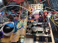
...so I'm attempting to power up the BA-3 and I'm not getting far......
I've got Antek 50VA 22V transformer-Salas BiB-BA3
I've wired 220R loads to both sides of the Salas shunt reg after building it, and can easily dial in 24V (or whatever else within reason) when connecting to the resistors.
When connected to the BA-3 I get no voltage out of the shunt reg. All the LEDs are lit but no volts across +F-0 or -F-0
I've checked the resistance for each V+ and V- to ground on the BA-3 and they are all around 500R or so....just as a sanity check for no obvious shorts.
I'm using a variac and bringing voltage up slowly (for obvious reasons).......when connected to the 220R load resistors, the voltage comes up and settles out around 24V as expected.....but getting nothing out when connected to BA-3
I have +F and +S going to both V+ on BA-3 for both channels and the grounds (both 0,0) going to a ground via on each channel.....same for negative voltage shunt side.......to the -V vias on both channels.
I've noticed that the grounds for each channel are not connected to the opposite channel, so I've tried powering up with a jumper between grounds on each channel...no go.
Since it's in breadboard form now I haven't tied all the grounds together and to the safety ground yet....not sure that's gonna make any difference.
I've pulled the leads off of the board and reconnected the 220R load R's...shunt works as expected.
Any ideas?
Attachments
The BA3 isn't biased up and therefore pulling no current, so I think the BiB is shunting all the power to ground.
If you have a bench supply, get the bias up and running and then power it with the BiB.
If you have a bench supply, get the bias up and running and then power it with the BiB.
You will need about three to four turns of P2 before you see current at R10 at least (same for P1 with R11) .
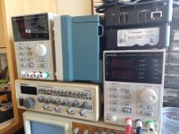
I found this video helpful: watchI have two bench supplies (they are the same) but they are not bi-polar......can I safely wire them to work as a bi-polar supply?
I've got the two bench supplies working as a bi-polar supply.....and I'm getting some bias voltage/current.....so far so good.....
I'll report back shortly....thanks everyone
I'll report back shortly....thanks everyone
Success! everything biased up fine....DC offset fine too... and shunt regulator works fine. But I'm still measuring next to no voltage at the shunt output connector..strange. I measure +/- 24V at the BA-3 V+ and V- so all is good.
Post your question on the PS here:
https://www.diyaudio.com/community/threads/salas-sslv1-3-ultrabib-shunt-regulator.322411/
https://www.diyaudio.com/community/threads/salas-sslv1-3-ultrabib-shunt-regulator.322411/
For future builders using IRF610/9610 mosfets........I started with 500R pots for P1/P2, but indeed had to switch to 1K pots to get enough bias current/voltage.
I've got the various components mounted in my chassis and have a potentially dumb question about wiring the inputs......
I have a typical rotary input selector, a Noble balance pot (100K R) that has the middle detent and a 50K Elma stepped attenuator....
Is there a preferred wiring between these two choices?
RCA-input selector-Balance-Volume-BA3
RCA-Volume-balance-input selector-BA3
I have a typical rotary input selector, a Noble balance pot (100K R) that has the middle detent and a 50K Elma stepped attenuator....
Is there a preferred wiring between these two choices?
RCA-input selector-Balance-Volume-BA3
RCA-Volume-balance-input selector-BA3
I ran into a couple of annoying details assembling my BA3 preamp yesterday and would like to query the assembled wisdom. Since this was to be my everyday user preamp for a while, hopefully long, I decided to treat myself to a Khozmo 64 step attenuator and the matching selector. I am looking forward to spoiling myself with remote control.
The basic configuration is Chassis #1: BA3 preamp board, Super regulator for BA3, attenuator and selector, and store filter board for the 5V to the attenuator and selector.
Chassis #2: Pearl 2 — of no further interest for this discussion
Chassis #3: Unregulated DC supplies, +-28V and return, regulated +5V and return, to Chassis 1, +-30V and return to Chassis 2. All three suppleis are independent and all returns are separate until they are tied to chassis ground in Chassis 3, exact means TBD (whatever sounds best).
The connection from Chassis 1 to Chassis 3 is through a harness comprised of a twisted pair for 5V and its return, three twisted wires for +-28V and return, an explicit chassis ground wire, and the overall harness is covered in a metal braid which is also chassis ground.
Everything was going well, and I was doing final safe to mate checks before installing the BA3 board when I noticed that things which should not be tied to chassis ground now were tied to chassis ground.
A few minutes of investigation revealed the following. The Khozmo attenuator takes +5V and return, and then has in, out, gnd for each channel. The attenuator ties 5V return to chassis! The signal grounds are floating, but 5V return is not.
The plot thickens, on the selector board there are three pads associated with each relay, two switched and one ground. I put a short length of twisted pair to each RCA connector, ~2 cm to one channel and ~4cm to the other. I had checked that all grounds were tied together and connected to the ground pad for the signal out. What I neglected to check was that those grounds were isolated from the 5V return on the board. You guessed right, they aren’t.
So the current state of things is that all the signal grounds are tied to 5V return which is then tied to chassis through the attenuator. This is not a happy state of affairs and I need to do something about it before final assembly. Most of it will be easy to fiddle with later, but the connections between the RCA inputs and the selector aren’t.
I think the first step is to lift all the grounds to the RCA connectors, tie each channel ground together and then run a short jumper to connect to the twisted pair currently connecting the selector output to the attenuator. All that ground path will now be isolated at the expense of a couple of inches of single ended wiring, but there are no AC sources in the box, so it should be OK.
The bigger question is what to do about 5V return. I had expected to make a hard connection from 5V return to chassis in the power supply. If I do that it is likely to be a lower impedance path than the return wire so there will be current flow through both 5V return and chassis. I could make the connection from the 5V supply to chassis through a resistor to raise that impedance and force most of the current back through the proper return wire. Or, I could mechanically isolate the attenuator body from the chassis. This would result in the attenuator body being grounded back through 5V return. This would also be a pain as there would be a lot of mechanical reworking to create space to move the attenuato.
I have an email in to Arek to see if what I am seeing is really the way it is supposed to be, but have not heard back from him.
Does anyone have any experience with these attenuators and can confirm that 5V return is tied to chassis?
Similarly signal ground on the selector and 5V return on selector?
Any thoughts on connecting 5V return to ground through a 1K resistor. That would almost guarantee that any chassis current would be well below 1mA. I guess I could also not tie 5V return to chassis in the Power supply box, but do it at the attenuator, but that seems a bit of a kludge.
- Home
- Amplifiers
- Pass Labs
- The BA-3 as preamp build guide