take my comments with a grain of salt as I am a total noob:
regarding the attenuator: measure the connectivity between a screwhole and the power pins?
regarding chassis ground: I would primarily care about signal ground and connect the +/-28V supply GND for the BA-3 like Papa does through a NTC (CL-60 or so) to a single point only on the preamp chassis. This is then your star ground for all signals.
Connect earth GND directly to PSU chassis and preamp chassis. If the 5 V GND is connected to the chassis via the attenuator or not, I would give it the same treatment and connect via 2nd CL-60 to the preamp chassis. This way everything is safe and the return currents flow in the return wire.

At these currents at CL-60 is a 10 Ohm resistor. There will never be enough current to change its temperature. There will be back to back diodes in there, but they only define a 0.7V grey area until they start to conduct. This is a small to very small signal application.
Consider the case of a CL-60 between 5V return and chassis. The 5V return wire of the attenuator is hard to the attenuator case, or at least as hard as can be measured two wire. I don't know the exact resistance of the 5V return, but it is ~2m of 20ga wire plus some pin contact resistance, call it a few tenths of an Ohm end to end. Chassis connects through the harness braid and the metal back shells, probably about the same or less. So now you have a voltage divider with a few tenths of an Ohm in parallel with a few tenths plus 10 Ohms. This will allow ~1-2% of the current to flow back through the chassis. The attenuator and selector draw something like 300mA steady state, so that is several mA on the chassis.
Consider the case of a CL-60 between 5V return and chassis. The 5V return wire of the attenuator is hard to the attenuator case, or at least as hard as can be measured two wire. I don't know the exact resistance of the 5V return, but it is ~2m of 20ga wire plus some pin contact resistance, call it a few tenths of an Ohm end to end. Chassis connects through the harness braid and the metal back shells, probably about the same or less. So now you have a voltage divider with a few tenths of an Ohm in parallel with a few tenths plus 10 Ohms. This will allow ~1-2% of the current to flow back through the chassis. The attenuator and selector draw something like 300mA steady state, so that is several mA on the chassis.
I would not worry about those few mA. Of course you can float everything, but I am not sure if thats a good idea. Choosing too high a resistance offers little protection, if something goes terribly wrong. The NTC seems to me like a proven solution and works for me, but others might have a different opinion.
You could mount the CL-60 for the 5V supply directly to one of the screwhole of the attenuator. This way you have almost no current on the chassis - remember the GNDs are only connected on the preamp chassis.
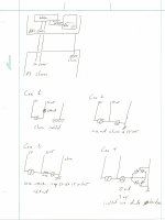
I made some measurements today. You can see a sketch of the test configuration in the attached. Current I is measured at the lab supply output.
Case 1: Isolated 5V and 5V return, I = 188mA, I(chassis) = 0
Case 2: 5V return hard connected to chassis, I = 187mA, I(chassis) = 12mA
Case 3: 5V return connected to chassis through CL-60 (~10Ohm), I = 186mA, I(chassis) = 6.8mA
Case 4: 5V return connected to chassis through diode bridge, I = 188μΑ, Ι(chassis) =0, 5V return to chassis ~3mV.
I plan on using two diode bridges, one for the selector and attenuator return to chassis and the second for the analog (BA3 and Pearl) returns to chassis. I think a few mV from 5V return to chassis will be OK, and a small price to pay for having no current return through the chassis. I did they a few things, but was not able to reduce the offset further. I also did a quick check with the scope and didn't see any egregious AC running around.
Attachments
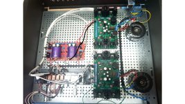
This is how my BA-3 is being assembled, the iSElect will allow for 3 switchable inputs, the builder said he'll do it all with one PSU and that's where I have my doubt as I wanted this to be a dual mono to match the dual mono build of the F4 power amp, what do you think about it?
Edit: I asked about to have twin output connections but my guy pointed correctly out that impedance would half, what would that cause in real life should I want one day to run biamp?

Edit: I asked about to have twin output connections but my guy pointed correctly out that impedance would half, what would that cause in real life should I want one day to run biamp?
Last edited:
The picture shows two bipolar supplies, with only one connected. When everything works, you can simply connect the 2nd supply for dual mono and judge, if you can hear a difference.
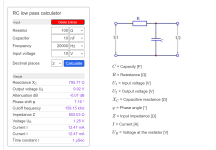
The output impedance seems to be around 100R for the BA-3, so you would have to use a really low input impedance on the amps and a really high cable capacitance to experience HF-roll off. Given a normal input impedance of above 47k on the amps and normal XLR or RCA interconnect I'd say you can easily hook up 10 amps or more in parallel. There are online calculators available that also show you if the phase shift, that comes before the roll off, would be an issue for the perfectionist. a calculator
My Aleph P with up to 2k output impedance works fine with 10 meter (admitttedly low impedance) cables into 48k.
In short: no worries hook 'em up
@ozorfis slow slow Ozofris, you probably got you dealing with a total newbie here, I wanted the BA-3 preamp to be dual mono to match the dual mono construction of the F4, I know it's just an expensive itch with probably no raise in quality but the expense was not that greater than a normal stereo construction so I went for it but my guy said that even one PSU (which outputs 29.x volts which should further lower the BA-3 distortion figure and allow more voltage swing to drive the no tension gain of the F4) does the job well, he said both are in use so that both get the same degree of "usage" should some day the other one be needed.
What I'd like to understand:
- before it is done and tuned, what does it mean to drive the board with just (...) one PSU rather than both
- and also about twin output to, some day, drive a biamp or two mono amps, impedance splitting into half, the amp am gonna use has 47K input impedance (if not wrong also the other amp I am using now, a push pull of KT88 tubes has the same input impedance), could that be a problem or is there something to implement in the preamp to smoothly use twin output?
Grazie
F4
Both channels left and right are fed by one PSU as shown in your picture.- before it is done and tuned, what does it mean to drive the board with just (...) one PSU rather than both
For dual mono each channel has its own PSU for greater channel separation and whatnot. Since you already have both PSUs in the chassis, just ask him to hook it up in dual mono. Why pay for a V8 and only drive on 4 cylinders?
Just ask for 2 RCA or XLR outputs wired in parallel so you have the possibility to connect the amps. You could lower the output impedance of the BA-3 by changing a resistor, which I would only do, if I had to. Use a short and or low capacitance cable to hook up your power amps and be happy. Disregarding inductive effects you can have 10 nF of total cable capacitance and still only have 7° phase shift or so. A good cable has 100 pF/m or so, which allows you torun 10 times 10 meters of cable in parallel to reach that 10 nF value.could that be a problem or is there something to implement in the preamp to smoothly use twin output?
Attachments
Hello Giovanni1968,
I would also hook up both powersupplies immediately - I have built my BA-3 preamp also dual mono a few years ago.
Your technician can adjust the voltages and the bias of the BA-3 in one go.
The main point is complete channel seperation from left to right - often better stereo imaging and depth...
My experience.
Cheers
Dirk
Sorry if I ask stupid questions, I am not onto the project since a while and almost forgot the whole thing so here they come the questions:
to wire the other PSU means, as by the draft, to just connect the three wires from the unused PSU to the BA-3 board as indicated in the above photo or does it take to also work on the other PSU?
In real life, if adding a second output by paralleling the RCA (balanced is not in the plans), given cables connecting the power amp(s) won't be longer than 3' or so, gonna be an issue?
Both the PSUs are wired and working, my friend told me there is enough juice to power it all with just one, I told him I want it as dual mono so next time we meet I will ask him to wire the second board and he sure knows how to do that but for my knowledge I won't mind some of you to waste a few minutes to explain what to change into wiring and what happens by using the two separate PSUs for each channel.
Grazie
You know the old saying, there are no stupid questions, but surely there are stupid answers. But I am not afraid of exposing my stupidity in public. 
Happy easter 🐰
Yes with the addition (which lazy me did not draw) of removing the already made connections from that channel to the old PSU. Each channel then has its own +29V Gnd and -29V and the channels can hardly influence each others supply voltages.to wire the other PSU means, as by the draft, to just connect the three wires from the unused PSU to the BA-3 board as indicated in the above photo
In my humble opinion absolutely not. You can make those cables even much longer and still be good. I have my amps close to the speakers so the interconnects are long but the speaker cables can be short as there are more issues to be had with the speaker cables and my crossovers.In real life, if adding a second output by paralleling the RCA (balanced is not in the plans), given cables connecting the power amp(s) won't be longer than 3' or so, gonna be an issue?
Happy easter 🐰
Molto chiaro @ozorfis it seems something which would take no longer than 10 minutes of desoldering, rewiring and soldering and I got it, a PSU for each channel so no mutual interference and, hopefully, a step towards a wider soundstage.
Today I had other stuff to do and a bit of dizziness, tomorrow I will begin by swapping tubes with the F4 and find out if the SP9 has enough gain to drive it until the BA-3 gets to the end.
Grazie e buona Pasqua a tutti
Today I had other stuff to do and a bit of dizziness, tomorrow I will begin by swapping tubes with the F4 and find out if the SP9 has enough gain to drive it until the BA-3 gets to the end.
Grazie e buona Pasqua a tutti
YEs @Dennis Hui it is here at home, went to pick it up yesterday and that's why now questions re the preamp, my friend Joe said that in his opinion some of the driver transistors probably broke during assembly and were replaced without to take the boards off the dissipators and as such not being correctly soldered, on the other channel also a transistor with a missing solder and it all made so the voltage not raising, he left it on for a whole night and measured the tension being 200.xxmV on the next day, biasing not easy as the Pot is very very sensitive but he achieved both bias and zero offset, now it's about to put it back in the system and find out how it sounds while waiting for the preamp to get done.
By the way he added a small BT module into the preamp so I can stream music off a BT compatible device for casual listening, a nice little token.
Grazie for checking
edit p.s. one of the mosfets for the BA-3 was dead so, just in case somebody is buying through one of the known sources here on the forum, please check onto arrival to make sure they are fine
Last edited:
It definitely is, didn't pay them cheap and they were supposed to be matched so I really don't believe they were even tested... fortunately my friend found some replacements in the UK if I recall it correct so matter of waiting for them to make it to here, wire the second PSU to the BA-3 board, fine tune the whole thing, close the lid and take it home in the hope the extra gain over the AR SP9 will give the needed push to the F4 and the JBL L220
Happy Easter everybody
Happy Easter everybody
So, finally the preamp got home, it still lacks final volume and input selector knobs but it made it home, it sure helped the F4 to sound more powerful than with the AR SP9 but not to a big magnitude.
Questions:
- I first tested it with the tube amp and there was a really loud hum, once switched to the F4 the hum is much lower and also higher in frequency, what might that be?
- the PSUs output 29.4V if I recall correct so it should be at the highest possible gain and lowest distortion figure, I'd like to test the output voltage to find out the gain, I remember somebody writing how to do it, input a sine in the preamp, volume pot to the max and measure the output on a channel, where can I find the correct procedure?
My friend who assembled it for me added a little token, a BlueTooth receiver so I can stream music off, say, a mobile phone to it, could that cause the hum?
Uff, seems this being a never ending story...
Have a nice weekend
Could be a ground loop or stray fields from the transformer or cables. You could disconnect everything from the preamp and hook the output up to a soundcard and record a FFT with free software like ARTA or REW. You can then see, if the preamp is silent or not and what the frequencies are. Alternatively you can hook up a good bench multimeter in the AC mV range and see what it says.- I first tested it with the tube amp and there was a really loud hum, once switched to the F4 the hum is much lower and also higher in frequency, what might that be?
Next you could take your multimeter in resistance mode and measure from the outer jacket of the RCA connectors to the chassis (preferably a screw or something without coating). Do the same thing for your power amps.
You can use any frequency generator, could be a bench device or an app for your phone or PC. The "standard" frequency is usually 1000 Hz. You can measure the output voltage of your smartphone/PC with a multimeter (preferrably true RMS one) set to AC Volts between the inner nipple and outer jacket of the RCA connector. Then hook the RCA cable up to your preamp, turn it up to 11, and measure on the output in the same manner. Stock gain of the BA-3 should be around 10 times or 20 dB - meaning if you put in 2 Volt you get out 20 Volts., I'd like to test the output voltage to find out the gain, I remember somebody writing how to do it, input a sine in the preamp, volume pot to the max and measure the output on a channel, where can I find the correct procedure?
No expert on this but HF wireless stuff can cause oscillations in high bandwidth amplifiers. Has your technician tested the preamp at his place and found it to be silent?BlueTooth receiver so I can stream music off, say, a mobile phone to it, could that cause the hum?
Solving such puzzles is part of the fun. Good luck

- Home
- Amplifiers
- Pass Labs
- The BA-3 as preamp build guide