Getting Ready to Turn this on
Months in the making, about ready to turn this on.
I think a 2.5 slow blow fuse is the correct one to use with a Antek AS--0520-50VA-20V transformer?
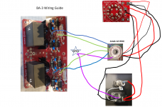
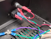
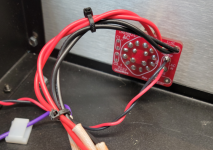
I've mapped all the wiring and have implemented accordingly. If anyone sees anything amiss, I'd appreciate it.
I have stumbled into a ground loop/hum issue on a different project, so I guess I'm trying to be extra careful here.
Months in the making, about ready to turn this on.
I think a 2.5 slow blow fuse is the correct one to use with a Antek AS--0520-50VA-20V transformer?
I've mapped all the wiring and have implemented accordingly. If anyone sees anything amiss, I'd appreciate it.
I have stumbled into a ground loop/hum issue on a different project, so I guess I'm trying to be extra careful here.
Attachments

50VA Donut calls for 50VA/115Vac=434mA
so take any of these - 300mA-315mA-400mA
Fast, why not
so take any of these - 300mA-315mA-400mA
Fast, why not
Chip,
That wiring guide is your old one with the fuse not wired correctly. I see that in your build your fuse is wired correctly.
If this is the first power-on test, you should first power up with a dim bulb tester. Also test in stages. Do not do your first power-on test with power supply and preamp boards all connected. Test your power supply first. If it works correctly then add one preamp channel. If that works then add the other channel.
and do not forget to bleed PSU caps, after initial PSU test
1K/1W is good enough for temporary bleeder
or even lesser power resistor, higher value - it'll just take more time to bleed
1K/1W is good enough for temporary bleeder
or even lesser power resistor, higher value - it'll just take more time to bleed
Chip,
That wiring guide is your old one with the fuse not wired correctly. I see that in your build your fuse is wired correctly.
If this is the first power-on test, you should first power up with a dim bulb tester. Also test in stages. Do not do your first power-on test with power supply and preamp boards all connected. Test your power supply first. If it works correctly then add one preamp channel. If that works then add the other channel.
Always start with dim bulb or be one. Check.
No connections to preamp board. Check
I grabbed the wrong drawing.
Thanks
I can confirm that bleedkng the psu-caps is good advice! (Mine sparked 2 days after initial test!)
Can i build the BA-3 pre in separate case and the BURNING AMPLIFIER COMPLEMENTARY BIAS AND OUTPUT SET FOR THE BA-2 & BA-3 in other case ?
I have seen them only together in the same housing.
I have seen them only together in the same housing.
or BURNING AMPLIFIER SINGLE-ENDED BIAS AND OUTPUT SET FOR THE BA-1 & BA-3
Is it possible?
and may i ask what is crippled F4?
Thank you in advance
Is it possible?
and may i ask what is crippled F4?
Thank you in advance
Last edited:
now sum your two last posts in one, so we can reply
I'm slightly confused what question is
🙂
yes, you can build FE in separate case
I'm slightly confused what question is
🙂
yes, you can build FE in separate case
i am sorry for that,
1) Can i build the BA-3 pre in separate case and
i) the Burning Amplifier Complementary Bias (BA-2 & BA-3) or
ii) Single-Ended output set (BA-1 & BA-3) in other case ?
2) may i ask what is crippled F4?
1) Can i build the BA-3 pre in separate case and
i) the Burning Amplifier Complementary Bias (BA-2 & BA-3) or
ii) Single-Ended output set (BA-1 & BA-3) in other case ?
2) may i ask what is crippled F4?
1. yes
i) why not ; as long you put OS and accompanying biasing circuit together, you don't need anything else to have functional power follower
ii) why not ; as long you put OS and accompanying biasing circuit together, you don't need anything else to have functional power follower
2. regular F4, sans input JFet buffer; you don't need it if you feed rest of amp (Crippled F4) with gain stage having sufficiently low Rout
I can confirm that bleedkng the psu-caps is good advice! (Mine sparked 2 days after initial test!)
Ok. I've youtubed bleeding capacitors and get the concept. But how to do it to capacitors installed on the PSU is a mystery to me?
what's wrong with using final/output pads on pcb?
they're usually in some continuity with caps 🙂
just take any size 2K resistor, and connect it from positive rail pad to negative rail pad
30secs and you're done
they're usually in some continuity with caps 🙂
just take any size 2K resistor, and connect it from positive rail pad to negative rail pad
30secs and you're done
Depending on the PSU boards you're using (like the ones sold in the store as an example).... they may even have a specific location for a bleeder resistor. Takes all the guesswork out.
Regulated PSU output drops ~4v when connecting the BA3 stage
Hello, I have just completed the building a BA3 gain stage and this is what I see.
Transformer is AS-1224 and using a simple LM317/337 regulated PSU. Before connecting the BA3 gain stage, I have adjusted the PSU output to +/- 24v. As soon as I connect the BA3 the output of the regulator drops to +/- 20v also if I measure the AC output of the transformer, there is a significant drop. I tried with different regulated PSUs and the result is the same.
I have connected the power supply via a 25watt lamp and the lamp turns on and goes off in a sec or so.
What could be the issue here? I don't see any component overheating. Any pointers on debugging would be of great help.
BA3 has been built using J313/K2013 and 500R pots. J74/K170 are matched around 8.5mA.
Thanks!
measure Vac of xformer under load, Vdc in front of regs
likely that you don't have enough voltage headroom; that under condition that everything is ok with load (line stage) and especially if rails sag is the same
likely that you don't have enough voltage headroom; that under condition that everything is ok with load (line stage) and especially if rails sag is the same
Thanks Zen Mod.
Under load, Vac of the transformer drops is 21vac and the Vdc in front of regs is 24vdc. The output after the regs is about 22v.
Without load, Vac is 24.9vac and Vdc in front of regs is 31vdc. The output after regs was set at 24v.
I tried setting up the bias / offset of the line stage and played some music through it. It seems to work well. Need to find out what causes the drop?
I have a 28vac transformer which I will try later tonight and see what the behavior is.
- Home
- Amplifiers
- Pass Labs
- The BA-3 as preamp build guide