Ok. Good to know. I will take it out.
Do you have a recommendations for suitable switches?
I will order the Lorlin RMS suggested earlier today.
I've been looking around but haven't found much.
Do you have a recommendations for suitable switches?
I will order the Lorlin RMS suggested earlier today.
I've been looking around but haven't found much.
@Chiptech
Are you SURE you have that switch wired correctly? I'm looking at budwiser's photo (post #2268)...his output wiring is the opposite of yours.
May not be the most robust switch in the world, but it shouldn't smoke under those conditions if wired correctly.
Are you SURE you have that switch wired correctly? I'm looking at budwiser's photo (post #2268)...his output wiring is the opposite of yours.
May not be the most robust switch in the world, but it shouldn't smoke under those conditions if wired correctly.
Last edited:
recommendations for suitable switches?
It is recommended to switch both hot and neutral, so a 2-pole switch.
The switch must be able to handle current and voltage, so, depending on what‘s behind it (line- or power-amp), you’ll need something in the range of 250V/1A up to 250v/>=4A
This explanation helps the search: Erlauterungen zu SPST, SPDT, DPST und DPDT - Littelfuse
And of course a round switch helps tremendously

Depending the look you’re after, you can choose between
Rocker switch
Rotary switch
Pushbutton
Or some fancy (electronic) stuff requiring some additional jigs, enabling many options (stand-by, touch-sensor, motion-sensor, etc etc)…
Chip,
I agree with others that you should order a switch with a higher current rating. However if you chose to test the Glassware mains switch again, I would disconnect everything downline. Once you have your switch connections sorted then connect the power supply and test. Only after the power supply checks out should you connect the BA-3 boards.
I agree with others that you should order a switch with a higher current rating. However if you chose to test the Glassware mains switch again, I would disconnect everything downline. Once you have your switch connections sorted then connect the power supply and test. Only after the power supply checks out should you connect the BA-3 boards.
I wasn't  beacuse of power rating of switch, what concerns me is that majority of switch body is metal in direct contact with case
open, contacts in close proximity to body........
same as you deliberately open big hole around your car seat, to enjoy in visage of asphalt flowing fast under your buttttt
beacuse of power rating of switch, what concerns me is that majority of switch body is metal in direct contact with caseopen, contacts in close proximity to body........
same as you deliberately open big hole around your car seat, to enjoy in visage of asphalt flowing fast under your buttttt
Chip,
I agree with others that you should order a switch with a higher current rating. However if you chose to test the Glassware mains switch again, I would disconnect everything downline. Once you have your switch connections sorted then connect the power supply and test. Only after the power supply checks out should you connect the BA-3 boards.
I rewired current into the switch. The dim bulb fades and then come's back on.
I think I'll wait for the new switch.
Attachments
to asilker #2289
Hello asilker,
I run my BA-3 - preamp on +- 32V. My bias is a bit below 1V over the bias resistors (R10 / R11).
One of my BA-3 - poweramps is running on +- 34.8V. This is close to the edge for the JFets on the BA-3 - frontend. 🙄 But they survive now for more than 3 years.
Cheers
Dirk 😀
Hello asilker,
I run my BA-3 - preamp on +- 32V. My bias is a bit below 1V over the bias resistors (R10 / R11).
One of my BA-3 - poweramps is running on +- 34.8V. This is close to the edge for the JFets on the BA-3 - frontend. 🙄 But they survive now for more than 3 years.
Cheers
Dirk 😀
to asilker
Sure, you can also lower the railvoltages.
It was designed to work best in the range around +-24V - rails.
The BA- 3 - frontend offers you the possibility to build an preamp with a lot of voltage swing.. It will also drive 'difficult' poweramps. If you don't need it -
go lower. Does it make sense? 🙄 hmmmm
Cheers
Dirk 😀
or look up at glassware what switch they recommend for the jig?
(FWIW, for rotary power-switches, I used lorlin: RMS – Lorlin Electronics — quite nice...)
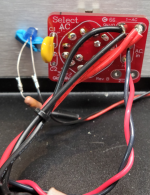
I received the Lorlin RMS switch, but I'm puzzled by how to connect up the wires. The datasheet doesn't indicate what's what. I'd appreciate your guidance.
thanks
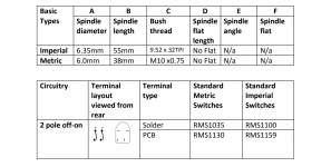
From the data sheet (https://lorlinelectronics.co.uk/wp-content/uploads/datasheets/RMS-ROTARY-MAINS-SWITCH-GB-Iss-A-190917-1.pdf):
The diagram of the back of the switch shows two switches (double pole single throw). Connect the hot to one of the two switches.
You can use your meter to check for on/off before proceeding.
The diagram of the back of the switch shows two switches (double pole single throw). Connect the hot to one of the two switches.
You can use your meter to check for on/off before proceeding.
Attachments
Use a meter to check the connections to see which connections go with which. There are 2 poles on this switch, so you have the option to wire hot only or both the hot and natural power coming into the pre. You just need to make sure that you identify which pole is connect to which. If you wire both poles and miss wire it. You can cause a short.
Use a dmm, measure topleft point against its left and bottom. If both are open, turn the switch and measure again, the pair indicating a closed circuit is channel one, the other pair channel 2…
Use upper or lower connectors for incoming (from the fuse/inlet), the other pair obviously to the next station.
Make triple sure you connected it correctly (in-out in-out, measure everything again—off state and on-state, and between the channels—after you connected the switch)…
Ah, of course this reply was way too late… 😀
Plus: the little image in the datasheet ben provided shows it pretty good: incoming on the switches’ round side, outgoing the other (square) side…
Last edited:
From the data sheet (https://lorlinelectronics.co.uk/wp-content/uploads/datasheets/RMS-ROTARY-MAINS-SWITCH-GB-Iss-A-190917-1.pdf):
The diagram of the back of the switch shows two switches (double pole single throw). Connect the hot to one of the two switches.
You can use your meter to check for on/off before proceeding.
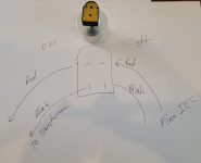
Thanks for all the great help. I've mapped out the wiring based on DMM readings.
Attachments
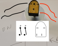
Even though you measured it, I suspect this is not the correct way, and would produce a short-circuit.
Are you really really sure you got a closed connection (a reading like 0.2 Ohm and not "OL")?
Sorry if I got it dead-wrong... but better a blame than a cooked amp...
Are you really really sure you got a closed connection (a reading like 0.2 Ohm and not "OL")?
Sorry if I got it dead-wrong... but better a blame than a cooked amp...
Attachments
Last edited:
I appreciate your help. When using two DMM's, one connected on the off side and one of the on side, when I turn the switch to the on position, both DMMs show 0.1 or 0.2. When I turn it off, they show OL. That is what my drawing maps.
When I hook them up as you have indicated, the DMM on the bottom two connections remains OL in the on position, and the DMM connected to the top two connections shows 31.85 M ohms.
My drawing assumes current flows from one side to the other vertically.
A bit confused at this end.
When I hook them up as you have indicated, the DMM on the bottom two connections remains OL in the on position, and the DMM connected to the top two connections shows 31.85 M ohms.
My drawing assumes current flows from one side to the other vertically.
A bit confused at this end.
- Home
- Amplifiers
- Pass Labs
- The BA-3 as preamp build guide