Well, this might be a good place to use Mark's soft-start PCB and on/off push button.
I went with the AC switch from Glassware as I had seen other's use it.
Ive used that switch, its the same one 6L6 used in the BA3 as preamp build guide.
Bubba
I appreciate your help. When using two DMM's, one connected on the off side and one of the on side, when I turn the switch to the on position, both DMMs show 0.1 or 0.2. When I turn it off, they show OL. That is what my drawing maps.
.......................
My drawing assumes current flows from one side to the other vertically.
A bit confused at this end.
If you have one meter connected to one side, that is a circuit on that side. So if current flows, then the current is flowing vertically from one meter probe to the other.
To lessen the confusion use only one meter.
Round Two
Testing the switch uninstalled, I got readings for the two horizontal connections, both OL with switch off, and 0.2 ohms with switch on.
With switch installed, I get OL reading across top of switch when off, and o.2 ohm with switch on. I get random readings from bottom connection with switch off or on. Is that because it is wired in?
Haven't tried the DBT yet.
Attachments
Chip,
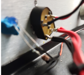
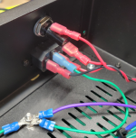
Based on the Data Sheet diagram of the switch and looking at your pictures, your wiring of the switch looks correct. See my mark-up showing the wiring as I see it on your pictures.
You said "Testing the switch uninstalled, I got readings for the two horizontal connections, both OL with switch off, and 0.2 ohms with switch on." If you had one probe on the top left and the other probe on the top right, then your readings do not seem possible based on the Data Sheet diagram of the switch.
As a check, place one meter probe on the top contact on one side of the switch, the other probe on the bottom contact on the same side of the switch. Measure the resistance with the switch On and Off. It should read Open with the switch Off and O Ohm with the switch On. Do the same on the other side of the switch.
Attachments
Ben,
Thanks for your help.
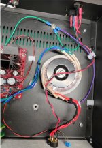
Looking at the switch inside of case:
on the right side [red] i get OL closed and 0.2 ohms open
on the left side [black] i get OL closed and 1.8 ohm open
Thanks for your help.
Looking at the switch inside of case:
on the right side [red] i get OL closed and 0.2 ohms open
on the left side [black] i get OL closed and 1.8 ohm open
A "closed" switch usually means the switch is in the "on" position.
An "open" switch usually means the switch is in the "off" position.
So for OL the switch should be in the "off" or "open" position and for zero or minimal resistance the switch should be in the "on" or "closed" position.
I assume that you measured OL with the switch "off" and 0.2 Ohm with the switch "on". If that is the case then the switch is as described in the Data Sheet.
Yes. I did.
I will attempt a DBT tomorrow.
open = off
closed = on
I have been conceptually challenged on this from the start.
But I've learned a few things too.
Thanks again.
I will attempt a DBT tomorrow.
open = off
closed = on
I have been conceptually challenged on this from the start.
But I've learned a few things too.
Thanks again.
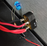
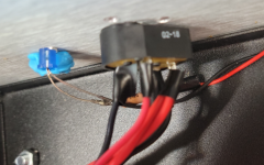
Do use heat shrink to cover as much of the bare wiring and pins as possible...as it is in the pic above it is VERY dangerous!

Last edited:
New Switch, Same Result
New switch, same problem
I ran the DBT test and got the same results: bulb dims and then brightens to steady on.
I started to take some AC readings, but I could smell something starting to cook, so turned it off.
I'd appreciate any thoughts.
New switch, same problem
I ran the DBT test and got the same results: bulb dims and then brightens to steady on.
I started to take some AC readings, but I could smell something starting to cook, so turned it off.
I'd appreciate any thoughts.
Attachments
What is connected? Everything, as in all boards and circuits? Or just the power supply?
I suggest testing in stages to isolate the problem.
1. Disconnect the transformer from the switch and test for AC at the switch output and test On and Off. If OK, then:
2. Connect the power supply only, test with DBT and voltmeter at DC out. If OK, then test with DBT removed and check voltage output. If Ok, then:
3. Connect preamp board, test with DBT.
Wait for ben to chime in.
In the meantime, check if you wired the toroid‘s primaries correctly:
Could it be that the primary 1 (red) gets the line treatment, and the primary 2 (black) gets the neutral treatment?
I never worked with dual primary-tranfos, but know that there are specific ways to hook them up depending on the voltage they receive (120V/240V)…
And again, apologies if I‘m nonsensing. It’s just that idea I had…
Could you smell where the smell came from?
Edit: he has already chimed in 🙂
Last edited:
What is connected? Everything, as in all boards and circuits? Or just the power supply?
I suggest testing in stages to isolate the problem.
1. Disconnect the transformer from the switch and test for AC at the switch output and test On and Off. If OK, then:
2. Connect the power supply only, test with DBT and voltmeter at DC out. If OK, then test with DBT removed and check voltage output. If Ok, then:
3. Connect preamp board, test with DBT.
Ben,
Thanks. I was testing thru to the transformer.
I will follow your steps and regroup.
thanks
Wait for ben to chime in.
In the meantime, check if you wired the toroid‘s primaries correctly:
Could it be that the primary 1 (red) gets the line treatment, and the primary 2 (black) gets the neutral treatment?
Your observation is above my pay grade. Hopefully someone else can clarify for me. I attempted to duplicate the wiring I have seen in the forum.
I never worked with dual primary-tranfos, but know that there are specific ways to hook them up depending on the voltage they receive (120V/240V)…
And again, apologies if I‘m nonsensing. It’s just that idea I had…
Could you smell where the smell came from?
Smell may have been coming from switch.
Turned it off too quickly to confirm.
Edit: he has already chimed in 🙂
the switch works
when off 120 V at input to switch
when on 120 v out of switch
20.7 volts at each secondary.
So something up with the PSU?
when off 120 V at input to switch
when on 120 v out of switch
20.7 volts at each secondary.
So something up with the PSU?
Possibly, so connect the power supply (without preamp PCB) with DBT and check.
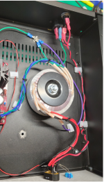
I am not familiar with the power supply but if you post clear focused pictures of it, I am sure someone that is familiar with it will look at it. Also include pictures of the overall setup so all wiring is visible for review.
I am not familiar with the power supply but if you post clear focused pictures of it, I am sure someone that is familiar with it will look at it. Also include pictures of the overall setup so all wiring is visible for review.
Ok boomer, go back and read the book
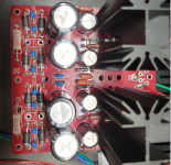
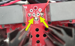
I think I've found my error.
See photos. I failed to install two jumpers which are required for the PSU to function.
So I will get them in and reinstall the board and test again.
Thanks for the help and I will update tomorrow.
I think I've found my error.
See photos. I failed to install two jumpers which are required for the PSU to function.
So I will get them in and reinstall the board and test again.
Thanks for the help and I will update tomorrow.
Attachments
- Home
- Amplifiers
- Pass Labs
- The BA-3 as preamp build guide