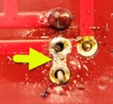
Well, I have the new pots. But in getting ready to put one in, I noticed that plastic between two of the leads has worn off due to aggressive removal of the previous ones. What you see in the photo is not solder between the two leads but, the red layer worn away. I think these two are linked anyway as part of the circuit?When you have the new pots in place, make sure you set them to minimum value before powering up.
Am I ok to use this board as is, or is it shot? I have one more pot with the same issue on this board.
Thanks
Attachments

Well, I have the new pots. But while installing the first one, I discovered that my aggressive removal of the previous pot has worn the plastic surface between two leads. See photo, what looks like solder is the trace between the two posts. Since they appear connected, can I still use this board, or is it time for a new one? I have one more issue like this on this board.When you have the new pots in place, make sure you set them to minimum value before powering up.
Thanks
Attachments
Thanks. How do I do a beep test? Always time to learn new things.It's likely fine. I'd beep test against the schematic to be certain.
buzzer test on your DMM
buzzing when R is lower than, say, 30 ohms
usually used to confirm short where it needs to be, but always take a look at screen to confirm practical 0 ohms, when needing it
buzzing when R is lower than, say, 30 ohms
usually used to confirm short where it needs to be, but always take a look at screen to confirm practical 0 ohms, when needing it

I can't tell exactly where that is on the board, and I don't have access to a good / big monitor.... but...
It looked to me like you just scraped off a bit of the solder mask across a short trace vs. lifted a trace, lifted a pad, or cut a trace. Someone else at a good screen can maybe confirm. Either way, you need to be sure yourself, and it's a good skill to have.
If you only scraped off the mask, then the trace will still have continuity to both pads. That's what you want. If you've lifted anything at the pads or the trace, you would have an open circuit.
Essentially:
Remove the relevant parts. You may have already done this, but I think I saw a lead still sticking through a hole.
Set your DMM to continuity. The meter will beep if you have a closed circuit (continuity) between the probes at a low enough resistance. It won't beep if there is no continuity (open) or if there is a high resistance.
The "Long way", and the correct way, is to check the board on the other side for the silkscreen designations for the parts that went into those holes.
Check the schematic to see whether you should or should not have a connection between any of those 3 points or not and verify using your meter.
The short way, and the way I'd do it, for your specific issue is to look at the traces and know that the two pads on the left are supposed to be connected. There is a visible trace between the pads. Make sure they still are connected. Poke your probes into the holes and make sure it beeps. It would be very surprising if it did not based on the pics.
Since it's close to your area of concern, put one probe into the hole on the right, and then alternate the other probe into the holes on the left. My guess is that you should not have continuity for those two measurements, but check the other side of the board for any traces between them. Check the schematic to see if there is supposed to be continuity between the two top pads. I can't tell in the pic.
Takes <30s for peace of mind, but I admit that it may be overkill.
Being able to check for unintentional shorts / open sections of a circuit against a schematic is a relatively simple part of troubleshooting / verification. Have fun 😀
Edited to add - that'll teach me to reply with a book when ZM's online.
........
Being able to check for unintentional shorts / open sections of a circuit against a schematic is a relatively simple part of troubleshooting / verification. Have fun 😀
Edited to add - that'll teach me to reply with a book when ZM's online.
Exactly. 👍
Identify the pot.
Find that pot on the schematic and check the wiring/connections. 🙂
Ben and ZM have a much more concise way of putting things. 😀 😀
Ben, does that look like where a pot goes though? Could be I'm not looking at it correctly, and I don't have access to my boards or good pics of a board on a monitor I can see well with right now.
Ben, does that look like where a pot goes though? Could be I'm not looking at it correctly, and I don't have access to my boards or good pics of a board on a monitor I can see well with right now.
I don't have a BA-3 preamp but looking at the pictures of the board and schematic, it looks like a pot location that allows for straight line and triangular pot leads.
Nice... you guys are awesome. 😀
So chiptech, if that's the case, then you should have one more lead to desolder (the top one?) and the two pads in the middle should have continuity (to each other and the bottom pad). See... don't go by my ability to see a picture. Go by the schematic. 😀 😀
So chiptech, if that's the case, then you should have one more lead to desolder (the top one?) and the two pads in the middle should have continuity (to each other and the bottom pad). See... don't go by my ability to see a picture. Go by the schematic. 😀 😀

I really appreciate all the guidance.
I'm a lot clearer on checking for continuity.
The two pots I have visual concern about are both P1's.
They both check with a buzz. Yeah!
The two P2 pots when tested each show 0.000 ohms. I don't have any reason to be concerned about them but found this curious.
I'm a lot clearer on checking for continuity.
The two pots I have visual concern about are both P1's.
They both check with a buzz. Yeah!
The two P2 pots when tested each show 0.000 ohms. I don't have any reason to be concerned about them but found this curious.
Just a teeny bit more 'help' perhaps. 😀 😀
When you're talking about measuring something, please try to be as specific as possible, and like you did above, whenever possible take a pic. It's tough for me to tell whether or not you should be concerned, curious, or happy about your 0.000 ohm results.
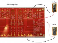
If you measured between the 4-pads / 3-pins while P2 was soldered to the board, and you got 0 ohms between a few of the pads, it would not give me pause, or make me curious. Similar to P1, three of the 4 pads are connected by traces, so you should. However, at least one set of checks should give an above-zero reading in circuit. Hint - it's the equivalent of measuring between either of the two "middle" pads and the "top" pad in your pic above. In the schematic below it shows the wiper of the pot connected to the end of the pot connected to the positive rail. The other end heads off to one end of R6 and the negative side of C1. The middle pads are for the wiper (the arrow in the schematic). You can also check the spec sheet of the pot. The bottom pad is the pad connected to the positive rail. You can verify that by seeing if there is continuity between any of those three pads (or all three) and the V+ pad on the board. 😀

With the pot out of the circuit, measuring between any two of the three pins should give you a reading > 0.000 ohms, and you might find a neat mathematical relationship between them. If you didn't, then that would be curious.
Given all that, and the fact that Ben clearly loves quizzes... 😈 Where do you think you should place your probes with the pot soldered onto the board to confirm that your new pots are at the lowest resistance before trying to bias it back up?
I type quickly and kind of with a train of thought. I hope that makes sense, and that it helps. When I get back to a better computer, I can put up a pic to take away a few thousand of my words if needed.
When you're talking about measuring something, please try to be as specific as possible, and like you did above, whenever possible take a pic. It's tough for me to tell whether or not you should be concerned, curious, or happy about your 0.000 ohm results.
If you measured between the 4-pads / 3-pins while P2 was soldered to the board, and you got 0 ohms between a few of the pads, it would not give me pause, or make me curious. Similar to P1, three of the 4 pads are connected by traces, so you should. However, at least one set of checks should give an above-zero reading in circuit. Hint - it's the equivalent of measuring between either of the two "middle" pads and the "top" pad in your pic above. In the schematic below it shows the wiper of the pot connected to the end of the pot connected to the positive rail. The other end heads off to one end of R6 and the negative side of C1. The middle pads are for the wiper (the arrow in the schematic). You can also check the spec sheet of the pot. The bottom pad is the pad connected to the positive rail. You can verify that by seeing if there is continuity between any of those three pads (or all three) and the V+ pad on the board. 😀
With the pot out of the circuit, measuring between any two of the three pins should give you a reading > 0.000 ohms, and you might find a neat mathematical relationship between them. If you didn't, then that would be curious.
Given all that, and the fact that Ben clearly loves quizzes... 😈 Where do you think you should place your probes with the pot soldered onto the board to confirm that your new pots are at the lowest resistance before trying to bias it back up?
I type quickly and kind of with a train of thought. I hope that makes sense, and that it helps. When I get back to a better computer, I can put up a pic to take away a few thousand of my words if needed.
I was hoping that Chip would look at the schematic and realize that two pins of the the pot are connected, and that the pcb has two pins of the pot connected (post #2344). 
Yep, I did understand that.I was hoping that Chip would look at the schematic and realize that two pins of the the pot are connected, and that the pcb has two pins of the pot connected (post #2344).
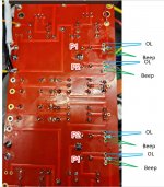
See photo below of my readings: Beep on two pins that are connected and OL on the other one.
I think I'm good to go.
Attachments
Well dang! Sorry, Ben. I blurted out the answer. No recess for me. Let's hope he didn't bother to read all of my blather. 😀 😀
Edited to add - Clearly he got it anyway. Simul-post.
Edited to add - Clearly he got it anyway. Simul-post.
Progress. Put everything back together. Wired the button start backwards. Fixed that.
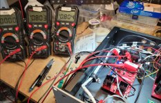
Getting readings around 0 .810 DCV on R10 & R12
Offset is minimal and never amounted to much as I adjusted the bias.
I'm using two different ways to read offset. I think I saw a recommendation to pull after the C3 cap. See photo.
Either way, not much offset showing up.
Am I missing something?
The sinks are both warm.
Attachments
- Home
- Amplifiers
- Pass Labs
- The BA-3 as preamp build guide