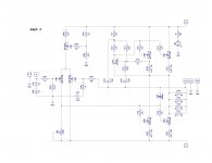
I designed a PCB to build an Aleph 3 clone. I transcribed the schematic Nelson posted early in this thread to DipTrace, which is my preferred software to design boards. I used the "Check Net Connectivity" and "Compare to Schematic" features in DipTrace to verify the PCB layout. No errors were detected.
I built one PCB and connected it. I can hear the music playing but it is distorted.
I measured only 0.31V across the source resistors. Removing R113 the voltage only increases to 0.42V.
The measurements I took while R113 (56K2) was still installed:
V+ +23.4V
V- -23.4V
Q105 Vce 3.8V
R106 5.1V
R108 4.3V
Z103 9.1V
Obviously I made a mistake somewhere, but I just can't find it. I have compared the transcribed schematic to the original, verified all transistor footprints to make sure they match the datasheets. As mentioned above, DipTrace does not indicate any discrepancy between the PCB layout and the schematic. Maybe the schematic has an error and I just can't see it. I am hoping somebody can help me spot it.
http://www.diyaudio.com/forums/attachment.php?attachmentid=663825&stc=1&d=1519168913
Attachments
DC offset is 0V. The input pair is tightly matched and I used a 500R trimpot for R108. Is it cheating? 🙂
On that subject, you once posted that to trim DC offset you preferred adjusting R106. Could you elaborate on that? My first impression is that changes to that resistor would affect Q101 and Q102 equally.
On that subject, you once posted that to trim DC offset you preferred adjusting R106. Could you elaborate on that? My first impression is that changes to that resistor would affect Q101 and Q102 equally.
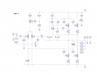
neg of C102 needs to be connected to Q105 emiter
Nelson usually offset the lines that connect to the same point. I did not see that in the schematic he posted. That means R104 and the negative of C103 are also connected to Q105's emitter, right?
Here is the modified schematic.
http://www.diyaudio.com/forums/attachment.php?attachmentid=663839&stc=1&d=1519172567
Attachments
I designed a PCB to build an Aleph 3 clone..........
it just came to me ......... that one is reaaaaaly reloaded

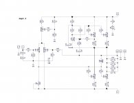
btw. you can trust me ......... or you can trust in some good schematics ....... result will be the same
regarding Papa's schematics ....... he used to be lazy sometimes , skipping few dots here and there
who knows , maybe it was deliberate , you know - pedagogy reasons

see attached schm ........ as far I remember - there was no mistakes , and there are plenty of nice details
regarding Papa's schematics ....... he used to be lazy sometimes , skipping few dots here and there
who knows , maybe it was deliberate , you know - pedagogy reasons
see attached schm ........ as far I remember - there was no mistakes , and there are plenty of nice details
Attachments
Could you explain your preference for trimming DC offset by adjusting R106?
not really preference ; just different way of skinning da cat
naah ...... I don't like that term
say - pealing da pineapple ......... 🙂
choose what you prefer more
it is Babelfish
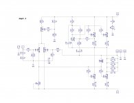
I meant - compare it with your schematic ........ it is practically same amplifier as any Papaleph , with few irrelevant differences , regarding principle
I meant - compare it with your schematic ........ it is practically same amplifier as any Papaleph , with few irrelevant differences , regarding principle
btw. you can trust me ......... or you can trust in some good schematics ....... result will be the same
regarding Papa's schematics ....... he used to be lazy sometimes , skipping few dots here and there
who knows , maybe it was deliberate , you know - pedagogy reasons
see attached schm ........ as far I remember - there was no mistakes , and there are plenty of nice details
I recall one (more?) of the original Aleph schemes having a fatal error 😱
Boy, that drove me nuts

The good news is that Zen Mod confirmed my schematic transcription is correct.
The not so good news is that the change he proposed only moves C102 negative connection to the inner side of the output current sensing resistors, effectively bypassing the equivalent 0R1 series resistance.
The bad news is that after hacking the PCB to implement the change, nothing really changed. The bias is still low, which I believe is causing the distorted sound.
- Home
- Amplifiers
- Pass Labs
- The Aleph Design Reloaded