Member
Joined 2009
Paid Member
Hi,
I think 100pF is a good starting point. You should be able to reduce this value during your experiments. You may find that C5 can be reduced to half that value.
Be careful about testing for stability as you play with compensation, I'm no expert but you need a dummy load to do it well and an oscilloscope will make it easier.
Member
Joined 2009
Paid Member
Maybe don't assume that the ceramic bypass caps to the main filter caps are always going to be good - read post 164
http://www.diyaudio.com/forums/power-supplies/240563-real-simulation-parasitics-5.html
I think it will be worthwhile to look at the power rails before adding additional bypass caps to see how clean they are.
http://www.diyaudio.com/forums/power-supplies/240563-real-simulation-parasitics-5.html
I think it will be worthwhile to look at the power rails before adding additional bypass caps to see how clean they are.
Member
Joined 2009
Paid Member
Fantastic !!!!
I feel nervous already - I hope we can get this working without major surgery.
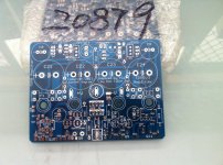
Looking at the pcb reminds that the plan with the axial power resistors is to mount them half a centimetre or so above the board for better air circulation and to allow you more space to squeeze everything in!
I feel nervous already - I hope we can get this working without major surgery.
Looking at the pcb reminds that the plan with the axial power resistors is to mount them half a centimetre or so above the board for better air circulation and to allow you more space to squeeze everything in!
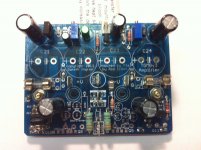
Okay... first board is stuffed.
Excuse the poor quality iPhone photos. The residue you see was left after I cleaned the board with PCB cleaner.... and I realised afterward the brush was contaminated with silicon grease. Grrrr 🙂
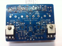
Anyhow it went together quite easily and the board didn't feel too cramped at all - nothing to worry about! I mounted the 1W resistors against the board and the 3W resistors with a ~1/4" air gap.
I haven't done any testing yet - that will have to wait until tomorrow or later in the week.
Excuse the poor quality iPhone photos. The residue you see was left after I cleaned the board with PCB cleaner.... and I realised afterward the brush was contaminated with silicon grease. Grrrr 🙂
Anyhow it went together quite easily and the board didn't feel too cramped at all - nothing to worry about! I mounted the 1W resistors against the board and the 3W resistors with a ~1/4" air gap.
I haven't done any testing yet - that will have to wait until tomorrow or later in the week.
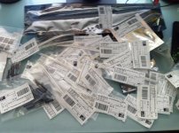
Attachments
Member
Joined 2009
Paid Member
Hi Gareth
You say in post #179 that the driver compensation cap (C10) is optional. I assume then that C11 is also optional since it also appears to be a compensation cap on the complimentary PNP driver.
Can I assume both C10 & C11 (driver compensationare optional?
Is there anyone in the Brisbane area with a sine wave generator and 'scope who would be interested in taking some measurements with the board?
Member
Joined 2009
Paid Member
Hi,
Looking at the P3a Rod finds that a comp cap is only needed on the one driver and only on the 'negative' side of the amplifier. I've heard this said before about the CFP output. I included one on the other driver in case I need it. Rod didn't use base stoppers either - they help ensure that the signal going into the base doesn't see a negative resistance which can happen depending on load conditions.
Have you applied power ? - it should be possible to see if it's completely mucked up or not by looking for sensible current flows and sensible voltages. Setting the idle current may be tricky, if it's too high it will get hot fast, if too low the CFPs tend to switch on an off harshly.
Safest way to start is to put some resistors in the power lines to the amp, or use the infamous 'bulb' or a current limited bench supply. You could take out the fuses, and 'wire wrap' a 100R power resistor in place of each one - at low idle current they shouldn't bake too quickly and measuring the voltage drop across them gives you an indication of the current flow in each power rail.
Last edited:
Thanks Gareth, I took a guess and omitted both C10 and C11 caps and I think that was the right decision for the time being.
I haven't applied power yet (only just had time to finish off the board). I probably won't another chance to spend time in the workshop until the weekend.
In terms I quiescent current, I was just planning to dial in around 50mV across the output collectors. But the Vbe offset - any suggestions?
I haven't applied power yet (only just had time to finish off the board). I probably won't another chance to spend time in the workshop until the weekend.
In terms I quiescent current, I was just planning to dial in around 50mV across the output collectors. But the Vbe offset - any suggestions?
Member
Joined 2009
Paid Member
Hi,
50mA sounds reasonable as a starting point - check what the P3A is set to.
Without C10 you may have oscillations - so tread carefully, look for unstable idle current (it will be sensitive to Vbe adjustments and hard to get it to stay stable), the zobel resistor might get hot, or the power devices might get hot. I think it's best to install C10, you can come back later and fine tune if you think a lower value than P3A will be better.
I haven't received my boards yet - shouldn't be long now.
Rod recommends the about 75mA which corresponds to around 50mV.
How do I set the Vbe multiplier?
How do I set the Vbe multiplier?
Is there anyone in the Brisbane area with a sine wave generator and 'scope who would be interested in taking some measurements with the board?
Try sending a PM to QUSP, I'd say he would have some kind of measurement equipment and is a very active member of DIYAUDIO.
Thanks lordearl. I've sent qusp a message requesting his assistance. Basically I'm hoping I can drop off my prototype to his house/work so he can perform measurements and post the results in this thread.
Looking at TGM8 v5 basic schematic, it's C11 (one on the BD140) that must be soldered and C10 can be omitted. Do not even think of omitting this cap. It must be soldered.
Member
Joined 2009
Paid Member
Start off with the Vbe trimpot at maximum resistance between base-emitter of the Vbe transitor - this will keep the transistor turned-on which will minimize the voltage across the collector-emitter which will minimize the current through the output - safest place to start off.
Test the PSU FIRST using the bulb tester.
When you are sure the voltages are correct and which are +ve or -ve, then power off and attach ONE channel of the amp and power up via the same bulb tester. Check your voltages and ensure all are as you would expect.
Only after that, try direct online power up.
When you are sure the voltages are correct and which are +ve or -ve, then power off and attach ONE channel of the amp and power up via the same bulb tester. Check your voltages and ensure all are as you would expect.
Only after that, try direct online power up.
Last edited:
- Home
- Amplifiers
- Solid State
- TGM8 - my best amplifier, incredible bass, clear highs, no fatigue (inspired by Rod Elliot P3a)