What does this mean ?
Mr. postman were around Yours home for some time 🙂


A.
Member
Joined 2009
Paid Member
The first batch of 10 boards has been ordered for direct shipment to Ranchu32 😀 
(My own order is waiting for me to finalize another board so I can combine the order. )
I added a small pad to the underside of the board adjacent to each 'mounting hole'. They are designed to allow me to use TO-126 devices as mounting washers. Seems a waste but they are just the right size and material. The idea is to cut off the outside leads, shorten the centre lead and lightly solder the stub to the little pad on the underside so as to hold the device to the board. This makes assembly easier. The pads are all connected to GND.
Last edited:
Thanks for organising this Bigun. Work has been busy this week but as soon as I get a chance I'll finalise the BOM and send off an order. If there are any Aussies here interested in a board to experiment with, let me know.
Member
Joined 2009
Paid Member
My boards are also on order. I 'cheaped out' and got the green whilst they were on sale. Nevertheless, I'm quite excited about it.
There is very a good chance that this will be my last solid state linear amplifier design so I hope t will work well enough to warrant me spending the time to make this one sing and bring it to a good conclusion.
There is very a good chance that this will be my last solid state linear amplifier design so I hope t will work well enough to warrant me spending the time to make this one sing and bring it to a good conclusion.
Gareth,
Are you going to help your public amplifier design discovery? I imagine a lot of people will miss that, and the forum will be the poorer for it...... OTOH, how many hidden manufacturers and designer are now exploiting your ideas? Was this your intent?
Cheers,
Hugh
Are you going to help your public amplifier design discovery? I imagine a lot of people will miss that, and the forum will be the poorer for it...... OTOH, how many hidden manufacturers and designer are now exploiting your ideas? Was this your intent?
Cheers,
Hugh
Member
Joined 2009
Paid Member
Gareth, have you given up on the SKA?
Not at all. When I ordered my TGM8 boards I also ordered a set of revised TGM7 (SKA) boards. If I can get SKA working to my satisfaction I'll build 5 channels of it for my home theatre.
Gareth,
Are you going to help your public amplifier design discovery? I imagine a lot of people will miss that, and the forum will be the poorer for it...... OTOH, how many hidden manufacturers and designer are now exploiting your ideas? Was this your intent?
Of course I am going to keep going with TGM8 and make myself a very nice stereo with it.
I won't be going away, I will do some more work with vacuum tubes, or a hybrid. I'm just trying to slow down a bit - this solid state stuff is fascinating, but it is sucking up hours and hours of my time to the detriment of other things in my life. Mind you, the last time I tried to take a break it lasted not too long before I was back into it.
Hidden manufacturers exploiting my ideas ? - I feel pretty sure I can trace all of my 'ideas' to something somebody else has already published on the internet. It takes more than ideas to make money in this industry - it takes some sweat and blood, a bit of risk taking, some marketing and perseverance. You should know 😀
Last edited:
Member
Joined 2009
Paid Member
I got email that my boards are finished processing. The boards for Ranchu32 must be taking a bit longer because of the colour request - perhaps they wait for enough orders to make some minimum amount. Anyhow good news is that it indicates they found no gross errors with the files I sent them. I will keep you posted !
Hidden manufacturers exploiting my ideas ? - I feel pretty sure I can trace all of my 'ideas' to something somebody else has already published on the internet. It takes more than ideas to make money in this industry - it takes some sweat and blood, a bit of risk taking, some marketing and perseverance. You should know 😀
100% true! That's why I was so surprised when Lazy Cat did not want to publish final circuit of VSSA. Publishing it would not make him lose a single buyer for his GB. The market is saturated with all kinds of audio products. No matter how good an amp is, industrially made or diy, it would require magic to make it top seller.
Hiya Bigun..
I have a little more time so I'm making some revisions to the BOM, which I'll be using for my own Digikey order shortly.
Do you think this FET is suitable for the speaker protect?
Invalid Request
Vdss = 100V; Id = 12.8A; Rds = 0R18 @ 6.4A, 10V
I'm pretty confident it can handle the power requirements of all variants, but wanted to double-check whether the Rds is low enough for your circuit?
Last edited:
Member
Joined 2009
Paid Member
I'm no expert on this but the way I see it is that the main concerns for higher Rds are a) heating of the device, b) reduced damping factor for the output.
Heating - say 3A rms through 0.18ohm is over 500mW. Of course, you are not likely to be running 3A rms very often or you'll go deaf. It'll probably be OK but until you try it at fairly high powers I can't say for sure how warm it will get.
Damping factor - you'll be adding 0.36 ohms in series with the output. I don't really take too much heed of damping factor concerns but it's a bit high for the purist. Ultimately it's probably speaker-dependent.
I don't think it will have any detrimental impacts on the amplifier circuit itself.
Last edited:
Unfortunately the part I originally spec'd in the BOM is on backorder.
I'll include this one instead, which has much better Rds than the one above.
Invalid Request
Vdss = 100V; Id = 42A; Rds = 0R037 @ 20A, 10V
I'll include this one instead, which has much better Rds than the one above.
Invalid Request
Vdss = 100V; Id = 42A; Rds = 0R037 @ 20A, 10V
Member
Joined 2009
Paid Member
Well that's a darn nuisance. The one you mention is very nicely priced though and looks good for the job.
I see there are a lot of nice alternatives if you want even higher spec (e.g. , FDPF190N15A-ND) but they are a couple of $ more expensive.
I see there are a lot of nice alternatives if you want even higher spec (e.g. , FDPF190N15A-ND) but they are a couple of $ more expensive.
Thanks Bigun. I'm trying to keep the BOM cost down without cutting too many corners.
I'm an engineer by training but an accountant by heart ;-)
I'm an engineer by training but an accountant by heart ;-)
I didn't order all the parts required for every option, only the 'basic' configuration, 2 pole VAS and speaker protection. So no MOSFETS or bulk filter caps at this stage. Also I have a small stockpile of Motorola power BJTs, which I will instead of the Toshiba devices specified in the BOM. The total order came in at just over A$200 (just over the minimum free shipping threshold) - but that is enough to fully populate 5 boards with a heap of leftover SMT resistors and other parts.
I've never really worked much with SMT so the parts bin is bare in that respect. Let me know if you need some SMT resistors; I've got 50 of each value on order so ample.
I've never really worked much with SMT so the parts bin is bare in that respect. Let me know if you need some SMT resistors; I've got 50 of each value on order so ample.
Member
Joined 2009
Paid Member
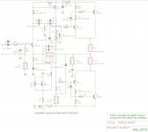
[...] only the 'basic' configuration, 2 pole VAS and speaker protection. So no MOSFETS [...]
For this option you are looking at a simpler schematic (attached - the speaker protection and power input are not shown to keep it uncluttered as those parts don't change).
Remember to keep within the voltage limits of your VAS, so if using BD140 then +/-36V is good whereas higher is stretching it.
VAS Compensation - I've never used two-pole before, the values I show are estimates. If you want to start really simple then leave R7 unpopulated and run it as a single pole Cdom style. You can still have both C4 and C6 in series if you like or you can replace one with a zero ohm link. You will find that the sound can be fine tuned by changing the VAS compensation but this should not be done to the point of compromising stability.
Phase lead compensation - the trick here is not to over-do it. I've shown C5 at 33pF and you likely don't want to go higher. If anything you want to try a little less and you can also try it without C5 populated. In practice, C5 reduces the amount of VAS compensation you might need.
Driver compensation - I included the option of a 'Cdom' on Q6. Rod doesn't find it necessary but I liked to have the option when building the enhanced VAS version which has higher OLG. You may not need to install C10 at all.
Nested feedback - R8 provides for feedback from the VAS. It will reduce the amount of feedback from the output stage. Therefore, it affects the overall compensation. It's optional, you can leave it off to start with. Including R8 may reduce the amount of VAS compensation needed for stability. It affects the behaviour of the amplifier in a subtle way and is another part that can be used to 'voice' the amplifier. If trying other values make bold changes, such as try half or twice the value.
The other part of the compensation is the output inductor, which goes off-board. You know that already.
Attachments
Last edited:
Thanks Bigun for your detailed explanation. I'm build the first board with a very simple topology, with R7 omitted, a single miller cap in C4, a wire link for C6, and a 33p cap in C5.
Do you think 100p is a reasonable starting point for the miller - or can you suggest some other value?
Do you think 100p is a reasonable starting point for the miller - or can you suggest some other value?
- Home
- Amplifiers
- Solid State
- TGM8 - my best amplifier, incredible bass, clear highs, no fatigue (inspired by Rod Elliot P3a)