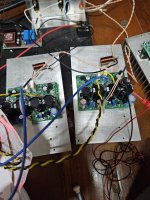
I assume you have checked all your soldering. Can you post good quality pics of the board(s) front and back? The group here have an uncanny knack for finding problems with some good pics.
What voltages are you seeing across R49 and R31,, is the negative voltage side conducting? Have you checked voltage across R20 and R23 to see if those BD139/140 are conducting?
This is some of the reading -vdc side behave normally. I just observed that the vdc+ is actually conduct current it responds to Bias trim but the bias current rises slowly about 1/10 compare to the -vdc side. Picture of board will follow, but I check with the working board and they are indentical.
Attachments
Member
Joined 2009
Paid Member
By the way, what voltage supply rails are you using?
More data points can help, hopefully something simple.
Assume the resistor values are correct ?
Odd biass behaviour can be caused by parastic oscillations, especially when working on a bench in an experimental mode of working, from having wires in a mess, output wires near input, near power rails, long ground wires, etc. has a way to punish you like that.
I assume you don't have an old pcb board where the silk screen labels were messed up and the biass pot and dc offset pot labels were swapped? That was a careless thing by me but fixed some years ago for all the design files.
Last edited:
It's 30vac around +/-42vdc. I have latest pcb and so far all resistors value are correct. Voltage readings quite stable, it responds to trim pot very well, no jumping around. Offset is adjustable and I can get it to be stable around <10mv. I will take all cpacitors out of the path way to ground and see what will happens.
Member
Joined 2009
Paid Member
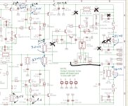
OK, so you see 100mA through R30 to the output node, and there’s no evidence of naughty oscillations so it is stable dc current which has to go somewhere to complete it’s circuit. It can’t be a bad C9 because you don’t see this much current in R15. It’s not R8 because the value is too high to flow 100mA with the voltages available. You don’t see it flowing through R31, so that leaves the following options to investigate:
R19 ( seems unlikely if the dc blocking cap C12 is good)
R10
D6 (not installed ?)
D7 (installed ? Correct polarity ? seems unlikely)
or, a rogue connection to the output that shouldn’t be there.
R19 ( seems unlikely if the dc blocking cap C12 is good)
R10
D6 (not installed ?)
D7 (installed ? Correct polarity ? seems unlikely)
or, a rogue connection to the output that shouldn’t be there.
Last edited:

Member
Joined 2009
Paid Member
Congratulations !
Your perseverance paid off, a bit of detective work. And now to enjoy the sound
Your perseverance paid off, a bit of detective work. And now to enjoy the sound
Member
Joined 2009
Paid Member
The first post mentions that the schematic I built is on post #604.
The CAD files also contain schematics.

The CAD files also contain schematics.
This is such a cool looking project, might attempt to build. Time has marched on though and it’s getting trickier to get the 1381 or any high speed/gain/low cob. I could get some of the Korean ones from a reputable reseller or stick with BD140/139 but is that sailing too close to the wind for above 40V rails?
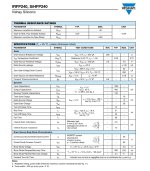
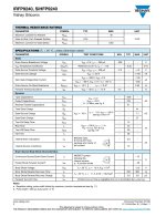
Found a possible alternative after some searching - PBHV9040X / PBHV8040X, released in 2013.
Only 7pF Cob, 500V, high gain and 55MHz. And cheap! SOT89 is all but happy to change the footprint, not a lot of dissipation though. Not sure how noisy. There’s also a 150V version, PBH9115X, 10pF Cob.
https://assets.nexperia.com/documents/data-sheet/PBHV9040X.pdf
Reckon these might work?
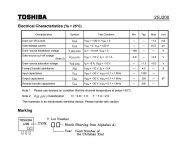
KEC has KTC3503-Y / KTA1381-Y as in-production equivalents to replace the out-of-production OnSemi KSC3503E / KSA1381E.
These can be sourced through Profusion. I believe they are currently in stock at Profusion.
These can be sourced through Profusion. I believe they are currently in stock at Profusion.
Member
Joined 2009
Paid Member
Maybe.
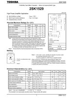
The resistor values that determine when the FETs turn on were set for the threshold voltage of the IRFP devices, but you can recalculate for devices of other threshold voltages if you want.
The gate capacitance of the FETs affects the high speed behaviour of the output stage, as it loads also the bipolar base drive. In particular, this affects the turn-off of the bipolars. This affects the high frequency shoot-through current and maybe audible.
It's all manageable, so in principle yes you can.
Can you post a comparison of the relevant numbers from the datasheets ?
Last edited:
Took me a second to realise your note regarding C3 & C8 isn't specifying "bipolar" capacitors but rather the BJTs they are next to? As you've used polar ones in the build? However the bootstrap capacitor C9 could see some reverse voltage, about 10V according to the sim before the amp clips. I wonder if a bipolar capacitor would be better there?
也许。
确定FET何时打开的电阻值是为IRFP器件的阈值电压设置的,但如果需要,可以为其他阈值电压的器件重新计算。
FET的栅极电容影响输出级的高速行为,因为它还负载双极基极驱动器,尤其影响双极的关断。 这会影响高频贯通电流,并且可能会听到。
这一切都是可管理的,所以原则上你可以。
您能否将数据表中的相关数字进行比较?
Attachments
Member
Joined 2009
Paid Member
The capacitances look compatible. The Toshiba data sheet gives cut off voltage (which is always lower than the Threshold voltage) whereas the Vishay sheet gives Threshold voltage so you can't compare them exactly. Nevertheless, I don't see harm in trying them as the Vishay parts will have some variation between batches anyhow.
Hi, Bigun. What is the thing with output bjt/mosfet pairs, is there a benefit, compared to double bjt pairs and what is it?The first post mentions that the schematic I built is on post #604.
The CAD files also contain schematics.View attachment 1458560
- Home
- Amplifiers
- Solid State
- TGM8 - my best amplifier, incredible bass, clear highs, no fatigue (inspired by Rod Elliot P3a)