About the lamps.
The link does not work (anymore), and so I think you must mean these:
12V Microlamps (2-Pack)
Model: 272-109, Catalog #: 2721092
I have some X-Mass ornament micro lamps left and will try those.
Tks!
The link does not work (anymore), and so I think you must mean these:
12V Microlamps (2-Pack)
Model: 272-109, Catalog #: 2721092
I have some X-Mass ornament micro lamps left and will try those.
Tks!
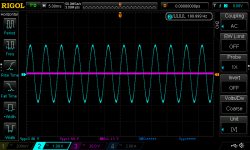
Looks good all the way through. Can't get measurements like that with D10 and D12 in place though :/ Without that, the interface loses a bit of its benefit. This is using a 2i2 for audio interface.
Which measurement software are you using?
Its not the diodes at the input that have been removed but the diodes before U8 (the output line driver) that are discussed these are sized to clip just slightly above the meter range causing not quite ideal use of the dynamic range on some soundcards.
I suggest that instead of removing D10/12, D11 / D12 be replaced by a string of 1N4148 diodes the number of is suitably selected to put the protection limit closer to the full scale voltage of the soundcard YOU are using.
Note: I got better THD (flatter increase) vs frequency by using THAT parts for the line recievers/drivers) (see posts a few pages back)
Did you mean replace D11 / D13?
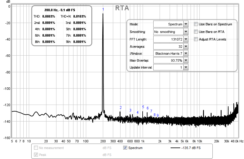
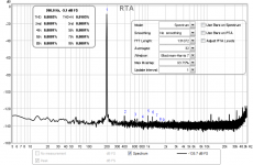
Hm, 200mv has noise floor at -142db, 2v at -125db, 20v at -129db and 200v at -143db... wish this was more consistent :/
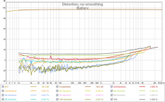
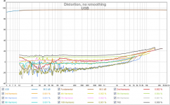
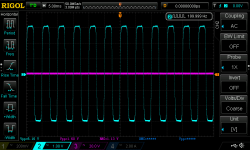
Here are some amp measurements before I static shocked my 2i2 to death :/ This is an emotiva Mini-X A-100 at -3db from max output, about 26 WPC @ 8 ohms
USB vs Battery power


USB vs Battery power
Attachments
Last edited:
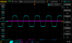
I added two more diodes inline with D11 and D13 and put D10 and D12 back. This causes the output signal to get clipped around 12Vpp

Attachments
Last edited:
About the lamps.
The link does not work (anymore), and so I think you must mean these:
12V Microlamps (2-Pack)
Model: 272-109, Catalog #: 2721092
I have some X-Mass ornament micro lamps left and will try those.
Tks!
I just switched these to xmas lights since they're meant for 120v and I didn't realize I grabbed the 12V lamps from radio shack... not that I think it will make a terrible difference, but I was curious.. They both end up measuring the same.
Hi,
also changed R2/R16 for light bulbs, and that gave another 6dB of improvement on the noise floor (using EMU 1616M)
@ Tazzz
what opamps did you use as input buffer (U4)?
best regards,
hallodeletue
also changed R2/R16 for light bulbs, and that gave another 6dB of improvement on the noise floor (using EMU 1616M)
@ Tazzz
what opamps did you use as input buffer (U4)?
best regards,
hallodeletue
I just switched these to xmas lights since they're meant for 120v and I didn't realize I grabbed the 12V lamps from radio shack... not that I think it will make a terrible difference, but I was curious.. They both end up measuring the same.
Make sure you use 120V bulbs... low-voltage bulbs have such low resistance that they won't provide any overvoltage protection.
Pete
Bulbs instead of R's
Well, 120V lamps are not so easy to find, at least not in the size we need.
The only ones I could find were these kind:
New Light Bulb for Whirlpool Maytag Kenmore Dryer 22002263 | eBay
These however pose problems because of the fittings.
Does anybody have a better one (with leads), or another idea?
Paul
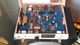
Hallodeletue, I see from your picture that you use little circuit boards with chips on them in place of the input resistors. Can you share that circuit with us? Is it better/equal to using lamps?
I also see a mod north of the DC-DC convertor, probably dealing with the DC input voltage. Care to share that with us?
Tks,
Paul
I also see a mod north of the DC-DC convertor, probably dealing with the DC input voltage. Care to share that with us?
Tks,
Paul
@paulwv that's tazz's picture. He's outlined a few of his changes in prior posts in this thread.
Make sure you use 120V bulbs... low-voltage bulbs have such low resistance that they won't provide any overvoltage protection.
Pete
Using the little christmas strand bulbs. Any suggestion for something more appropriate?
- Home
- Design & Build
- Equipment & Tools
- Test & Measurement interface for Soundcard