For the 2SC5171, you do not need exactly such a high end device.
Any 100V-type with current gain > 100 will do.
U101:
Special Purpose | Isolators | DigiKey
U102:
Choose your preferred dual Audio OP amp which has the same pinning and is unity gain stable.
Preferably look to types with JFet inputs, but that's not a must.
Any 100V-type with current gain > 100 will do.
U101:
Special Purpose | Isolators | DigiKey
U102:
Choose your preferred dual Audio OP amp which has the same pinning and is unity gain stable.
Preferably look to types with JFet inputs, but that's not a must.
For 2SC5171 replacement
Like these?
Manufacturer Part #: ZTX753 , BD240CTU, KSB546YTU, ZTX753STZ
Like these?
Manufacturer Part #: ZTX753 , BD240CTU, KSB546YTU, ZTX753STZ
- ..the BD240C has not much guaranteed current gain. But has a reasonable good chance to work, because typically they are much better than guaranteed.
- The Zetex types - cannot handle the heat (...even if I did not mention anything about the power rating... You are kidding - right?)
KSB546YTU is PNP, while the 2SC5171 is NPN ! Now I am sure, you are kidding me... 😉
- The Zetex types - cannot handle the heat (...even if I did not mention anything about the power rating... You are kidding - right?)
KSB546YTU is PNP, while the 2SC5171 is NPN ! Now I am sure, you are kidding me... 😉
I am not kidding. I just don't know much but I am enthuziast 🙂. I am new in this field (approx. 1 year) coming from a very different world.... I used "similar product search" and I didn't refined enough the results. Thank you again for patience and answers.
So, may I use the BD240C for For 2SC5171 replacement? Maybe better 2SA1930(Q,M) available in September?
For U101 - NSL-32 I think there is nothing equivalent on Mouser so I must find another way to get it
For U103 may I use TL084ID?
@twest820: U102 is already in the order thank you. Ui101 and U103 was the difficulties.
.
D
Deleted member 148505
Hi Chocoholic, I'm interested in replicating your test measurements for switching wave shapes specially #3,4,5,6. What kind of load resistor did you use, can you show your test rig with the test module wired with power supply and load resistor?, and how long is it safe to run the module in that condition without overheating the mosfets / load resistors. What interesting wave shapes and behavior to look at.Examination of switching wave shapes:
Amp without input signal (input shorted).
1) Idle/no load, event of turning off the low side MosFet
2) Idle/no load, event of turning on the low side MosFet
3) Sink load current. Resistor from pos rail to amp output, event of turning off the low side switch.
4) Sink load current. Resistor from pos rail to amp output, event of turning on the low side switch.
5) Source load current. Resistor from neg rail to amp output, event of turning off the low side switch.
6) Source load current. Resistor from neg rail to amp output, event of turning on the low side switch.
Typically, I do not have the load towards the rail connected when staring up the amp, but connect it manual just for the short time of doing the measurement. Easy for the LiteAmp, but for the 2kW monster and involved currents and voltages this game always was an impressive welding event at the contact point.... Better wear glasses.
Alternatively you could use some proper electronic relay, but the arcing during the manual test can also be seen as a ruggedness test.
For measurements 3,4,5,6 start with reasonably small currents, because untamed and badly ringing half bridges will burn at higher currents.
Interesting current levels start when the load current is larger than the filter ripple current.
So measure - adjust - measure - adjust- measure - increase load - measure - ....
If you use an isolated floating power supply, then all this can be done even without the need of differential probes.
Do not try to simulate equivalent situations by applying DC to the amp input with load from amp output to GND. DC signal and load to GND would cause heavy bus pumping!
Thanks and regards,
Lester
Last edited by a moderator:
...understood, you are jumping into a DIY adventure.... but I am enthuziast 🙂. I am new in this field (approx. 1 year) coming from a very different world...
I will give as much remote support as possible, however once and a while
some delay in my answers may happen.
You cannot substitute 2SC5171 by 2SA1930.So, may I use the BD240C for For 2SC5171 replacement? Maybe better 2SA1930(Q,M) available in September?
They are both complementary types to each other.
However in this application it will work to substitute 2SC5171 with a BD239C
and to substitute the 2SA1930 with a BD240C.
Please note: In my last answer I did not properly see that you intended to substitute an NPN (2SC5171) with PNP (BD240C).
Yes. Not tested, but from theory TL084 is perfectly fine for this.For U103 may I use TL084ID?
PCBs arrived today, perfect quality
Thanks for the Optos CHOCO!!
Small problem that I have to order the SMD resistors for the Gain board.
Thanks
Thanks for the Optos CHOCO!!
Small problem that I have to order the SMD resistors for the Gain board.
Thanks
What kind of load resistor did you use, can you show your test rig with the test module wired with power supply and load resistor?, and how long is it safe to run the module in that condition without overheating the mosfets / load resistors. What interesting wave shapes and behavior to look at.
Hi Lester,
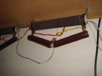
I do not have any special test rig, I am just using ordinary high power resistors and combine them in order to get the required resistance and power rating.
I.e. mounted below my workbench there are two resistor triples as shown in the attached picture. Each of this triples results in 4R capable of roughly 200W with some forced ventilation. With this 2x 4R I can get easily 2R, 4R, 8R - simply by series or parallel connection. If I need other values, I have to settle specific other resistor combinations...
Besides the resistor picture, I am also attaching a schematic showing the connection circuitry.
The down side of this method is that you need an extremely strong PSU already for moderate amps.
Consider the LiteAmp tested at 20A. Drawing this from 40V. The PSU and the resistor are stressed with 800W.
For larger amps usually you sinply do not have sufficient PSU and resistors to test this way.
But there is a simple trick for reducing the involved power, but stressing the amp with high currents.
Instead of giving zero input signal, you can jumper the input coupling cap(s) and feed a small DC voltage to the amp input.
I.e. if you have +/-40V rail, you can give a little DC input voltage bringing the output of the amp to +30V. Difference vs +40V is now just 10V (if rail does not sag). When now putting 0.5R between output and rail you will stress the amp 20A, but the PSU is not much loaded (200W only), because the switch mode amp will feed back a lot of current to the rail.
Always start with moderate currents, at high currents this measurement is really tough for the amp!
Duration of this test is short. Just some seconds, which you need to get the reading. When you stress the amp close to the shut down limit and use ASICs like the modern IRS types, which measure the drop across the Rdson, then you will observe a temperature effect.
Within few seconds the Rdson grows, which will then trigger the shut down.
If you do not have a reliable shut down, keep good margin vs max current with this measurement.
Interesting wave shapes:
If you are only interested in the switching behavior and taming HF resonances of the half bridge, then it is sufficient to measure the Vgs and Vds of the low side MosFet.
These two signals tell you 99% of the story.
If you also want to see the dead time under load conditons, you will have to measure the Vgs of the upper MosFet as well.
This either calls for a differential probe and a scope with deskew for the timedelay of the differential probe or a 4 chanel scope with large overdrive headroom and chanel substraction (Vg of upper Mos Fet vs neg rail minus Vds of lower MosFet).
Correct probe connections (do not use their long GND clips, but direct GND connection from the tip) and correct adjustment of the probes are essential for all these measurements.
Attachments
PCBs arrived today, perfect quality
Thanks for the Optos CHOCO!!
Small problem that I have to order the SMD resistors for the Gain board.
Thanks
Thanks for confirmation.
 ..this really was a long travel with snail mail.. !
D
Deleted member 148505
Hi Lester,
I do not have any special test rig, I am just using ordinary high power resistors and combine them in order to get the required resistance and power rating.
I.e. mounted below my workbench there are two resistor triples as shown in the attached picture. Each of this triples results in 4R capable of roughly 200W with some forced ventilation. With this 2x 4R I can get easily 2R, 4R, 8R - simply by series or parallel connection. If I need other values, I have to settle specific other resistor combinations...
Besides the resistor picture, I am also attaching a schematic showing the connection circuitry.
The down side of this method is that you need an extremely strong PSU already for moderate amps.
Consider the LiteAmp tested at 20A. Drawing this from 40V. The PSU and the resistor are stressed with 800W.
For larger amps usually you sinply do not have sufficient PSU and resistors to test this way.
But there is a simple trick for reducing the involved power, but stressing the amp with high currents.
Instead of giving zero input signal, you can jumper the input coupling cap(s) and feed a small DC voltage to the amp input.
I.e. if you have +/-40V rail, you can give a little DC input voltage bringing the output of the amp to +30V. Difference vs +40V is now just 10V (if rail does not sag). When now putting 0.5R between output and rail you will stress the amp 20A, but the PSU is not much loaded (200W only), because the switch mode amp will feed back a lot of current to the rail.
Always start with moderate currents, at high currents this measurement is really tough for the amp!
Duration of this test is short. Just some seconds, which you need to get the reading. When you stress the amp close to the shut down limit and use ASICs like the modern IRS types, which measure the drop across the Rdson, then you will observe a temperature effect.
Within few seconds the Rdson grows, which will then trigger the shut down.
If you do not have a reliable shut down, keep good margin vs max current with this measurement.
Interesting wave shapes:
If you are only interested in the switching behavior and taming HF resonances of the half bridge, then it is sufficient to measure the Vgs and Vds of the low side MosFet.
These two signals tell you 99% of the story.
If you also want to see the dead time under load conditons, you will have to measure the Vgs of the upper MosFet as well.
This either calls for a differential probe and a scope with deskew for the timedelay of the differential probe or a 4 chanel scope with large overdrive headroom and chanel substraction (Vg of upper Mos Fet vs neg rail minus Vds of lower MosFet).
Correct probe connections (do not use their long GND clips, but direct GND connection from the tip) and correct adjustment of the probes are essential for all these measurements.
Thank you for sharing info and answering my question even though I am not building your amp, really helpful for class-d starters. Schematic is helpful in getting the test correctly. Without it my amp might go boom😱.
can someone please advise on a suitable C110 (gain board) at mouser? the lowest leakage current i could find was 2uA?
thanks
thanks
2uA is already at the lower end which manufacturers will guarantee.
The leakage is strongly depending on temperature and operating voltage.
I had chosen a 100V / 105°C / 5uA type and selected manually for low leakage.
Counted Ok everything below 30nA at 5V and 25°C.
Also tested some of them at 85°C ad found them around 100...150nA.
Another option is to use ceramic SMD types of size 0805.
This size fits for manual soldering to the through hole pads of C110.
The advantage is that you do not need to select for low leakage.
Ceramics X7R have much lower leakage.
I.e.:
C2012X7R1C475K125AE TDK | Mouser
Hi Marcus
Thought you deserved to see how my build was progressing.
I really wonder if C23 , C24, C25 , C26 in your board are 250VDC.
SB1100 has a slightly higher capacitance, nevertheless from theory it should easily work without trouble.
LiteAmp Family
Here the LiteAmp family. All versions are fitting to the same PCB.
Furtheron it is time to fully publish also the Gerber Data.
For the higher voltages a detailed analysis of the switching stress and the capabilities of the IRFI4020 showed that already at 2x75V a 4R load would be too much of stretch for my taste.
My examinations showed that 2x70V and 8R with one IRFI4020 is more or less the limit for a reasonable design, which is similar to the choice of IR in their reference designs.
The LiteAmp has two IRFI devices in parallel, it has to be taken into account that load sharing will not allways be half/half due to component tolerances.
So I settled a version for 2x65V at 4R and a version for 2x80V at 8R.
GainBoard:
In order to tame the noisy OTA of the IRS2092, all the LiteAmps are designed for large input signals (ranging from 6.5Vp to 8Vp for max.power).
The gain board offers differential inputs for typical line levels and is able to drive the LiteAmp to full power.
It also incorporates a limiter, which avoids amp clipping. (If not needed, the limiter can be skipped.)
Documentation has it focus on 2x40V, but includes the rules for adjustment to any other supply.
2x40V_IRFI4212:
This Version has been shown in very detail over the previous part of the thread.
Possible operating range: 2x25V...2x42V
Max. power at stabilized 2x42V: 400W / 2R
Power with realistically sagging supplies, idling at 2x40V:
250W/2R, 130W/4R, 70W/8R
2x80V_IRFI4020:
Slightly less audiophile than the 2x40V-version, but still better than average.
Attached harmonics measurements are for 1W and 200W.
Possible operating range: 2x50V...2x84V
Max. power at stabilized 2x84V: 400W / 8R
Power with realistically sagging supplies, idling at 2x80V:
250W/8R (not suited for 4R and 2R !)
2x65V_IRFI4020:
Like the 2x80V, but over current protection allows operation at 4R.
Possible operating range: 2x40V...2x68V
Max. power at stabilized 2x68V: 500W / 4R
Power with realistically sagging supplies, idling at 2x65V:
300W/4R, 160W/8R (not suited for 2R !)
Attachments
-
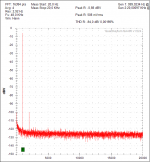 80V_IRFI4020_1W_8R.png31.2 KB · Views: 842
 -
LiteAmpMainGerber20140724.zip77.3 KB · Views: 252
-
LiteAmp2x80V_IRFI4020_BomBuilderData.pdf326.2 KB · Views: 282
-
LiteAmp2x65V_IRFI4020_BomBuilderData.pdf305.5 KB · Views: 267
-
LiteAmp2x40V_IRFI4212_BomBuilderData.pdf435.7 KB · Views: 308
-
LiteAmp_2x40V_IRFI4212_Schematic.pdf114.8 KB · Views: 433
-
LiteAmpGainGerber20141121.zip58.3 KB · Views: 240
-
LiteAmpGainBoardBOM20141121.pdf256.6 KB · Views: 308
-
LiteAmpGain_2x40V_Schematic20141124.pdf95.6 KB · Views: 452
-
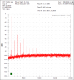 80V_IRFI4020_200W_8R.png31.3 KB · Views: 850
Last edited:
- Home
- Amplifiers
- Class D
- SystemD LiteAmp