Devil in the detail ... missed to update snubbers in the BOM
The devil's in the detail. Really!
With the changed more heavy MosFets for higher voltages also the snubbers needed an adjustment, but I missed that in the BOM!
Take care, not just the values changed, but also voltage and power ratings.
Here the updated BOMs for 2x65V and 2x80V.
Settling an error free BOM often needs some loops, in case you notice/suspect errors, please let me know.
Attachments
 Many thanks goes to Markus for sharing this ultra nice amplifier with us.
BR Toni
P.S. Is it possible to use 2 x IRFI4019 instead of IRFI4020 if build for 8R usage only?
P.P.S.: 4 Channel bridged Class D LiteAmp is playing fine every day!
Hello Astx
greetings is it possible to share your bridging schematic
warm regards
Andrew
Have a look at posts #
- 242: bridging adaptor with gain
- 364 and 365: bridging adapter without gain
BR, Toni
Last edited:
Hello Astx
greetings thank you for replying i have all the parts with me in my junk box
even LM4562 will design the pcb right away
thanking you
Andrew
greetings thank you for replying i have all the parts with me in my junk box
even LM4562 will design the pcb right away
thanking you
Andrew
P.S. Is it possible to use 2 x IRFI4019 instead of IRFI4020 if build for 8R usage only?
You mean building 2x65V_IRFI4020 and simply replace the IRFI4020 with the IRFI4019?
Change of MosFets is always good for surprises, but from theory both devices appear close enough that it should work and I think up to 2x60V it should be fine even with a 4R load and unchanged overcurrent setting.
You mean building 2x65V_IRFI4020 and simply replace the IRFI4020 with the IRFI4019?
...
Dear Markus,
this is exactly what I meant. I have "tons" of unused IRFI4019 from an unfinished IRS2092 project and this would be a very good option to recycle them.
Br, Toni
Very nice build Chocoholic,
Can someone please point me towards the post showing Amplitude Vs Frequency response with variety of loads say 2, 4, 8 ohm and also open load response. I am curious to see the behavior of this post filter feedback. I have seen the pre-filter feedback response gives peaking at HF.
Can someone please point me towards the post showing Amplitude Vs Frequency response with variety of loads say 2, 4, 8 ohm and also open load response. I am curious to see the behavior of this post filter feedback. I have seen the pre-filter feedback response gives peaking at HF.
Here the LiteAmp family. All versions are fitting to the same PCB.
Furtheron it is time to fully publish also the Gerber Data.
For the higher voltages a detailed analysis of the switching stress and the capabilities of the IRFI4020 showed that already at 2x75V a 4R load would be too much of stretch for my taste.
My examinations showed that 2x70V and 8R with one IRFI4020 is more or less the limit for a reasonable design, which is similar to the choice of IR in their reference designs.
The LiteAmp has two IRFI devices in parallel, it has to be taken into account that load sharing will not allways be half/half due to component tolerances.
So I settled a version for 2x65V at 4R and a version for 2x80V at 8R.
GainBoard:
In order to tame the noisy OTA of the IRS2092, all the LiteAmps are designed for large input signals (ranging from 6.5Vp to 8Vp for max.power).
The gain board offers differential inputs for typical line levels and is able to drive the LiteAmp to full power.
It also incorporates a limiter, which avoids amp clipping. (If not needed, the limiter can be skipped.)
Documentation has it focus on 2x40V, but includes the rules for adjustment to any other supply.
2x40V_IRFI4212:
This Version has been shown in very detail over the previous part of the thread.
Possible operating range: 2x25V...2x42V
Max. power at stabilized 2x42V: 400W / 2R
Power with realistically sagging supplies, idling at 2x40V:
250W/2R, 130W/4R, 70W/8R
2x80V_IRFI4020:
Slightly less audiophile than the 2x40V-version, but still better than average.
Attached harmonics measurements are for 1W and 200W.
Possible operating range: 2x50V...2x84V
Max. power at stabilized 2x84V: 400W / 8R
Power with realistically sagging supplies, idling at 2x80V:
250W/8R (not suited for 4R and 2R !)
2x65V_IRFI4020:
Like the 2x80V, but over current protection allows operation at 4R.
Possible operating range: 2x40V...2x68V
Max. power at stabilized 2x68V: 500W / 4R
Power with realistically sagging supplies, idling at 2x65V:
300W/4R, 160W/8R (not suited for 2R !)
Nice one Marcus!.
Now if only someone could design a "safe" cheap to construct SMPS to pair with this project.
If our Rand currency wasn't so weak 1R = $14,I would be getting involved in another build, but economics is hutting our wallets at the moment in South Africa

Nice one Marcus!.
Now if only someone could design a "safe" cheap to construct SMPS to pair with this project.
If our Rand currency wasn't so weak 1R = $14,I would be getting involved in another build, but economics is hutting our wallets at the moment in South Africa
I could offer two unregulated SMPS units at 120US$ for both units (exclude shipping), 600W Continous,, 1000W Peak.
Size is 12x11CM
Regards
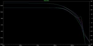
... post showing Amplitude Vs Frequency response with variety of loads say 2, 4, 8 ohm and also open load response.
The filters in front of my QA400 are to slow for a correct measurement.
From design theory the 2x40V version shows a flat gain of 13.9db (+0.1db / -0.5db) up to 26kHz.
-3db bandwidth is larger than 60kHz with any load.
The graph is showing gain and phase at 2R, 4R, 8R, 99999R.
Attached also the LTspice file with the averaged model for AC analysis.
Feel free to simulate the other versions.
Attachments
The filters in front of my QA400 are to slow for a correct measurement.
From design theory the 2x40V version shows a flat gain of 13.9db (+0.1db / -0.5db) up to 26kHz.
-3db bandwidth is larger than 60kHz with any load.
The graph is showing gain and phase at 2R, 4R, 8R, 99999R.
Attached also the LTspice file with the averaged model for AC analysis.
Feel free to simulate the other versions.
Very nice Choco,
looks like Zobel is mandatory part of the response, omiting it causes peaky response with open loads.
The filters in front of my QA400 are to slow for a correct measurement.
From design theory the 2x40V version shows a flat gain of 13.9db (+0.1db / -0.5db) up to 26kHz.
-3db bandwidth is larger than 60kHz with any load.
The graph is showing gain and phase at 2R, 4R, 8R, 99999R.
Attached also the LTspice file with the averaged model for AC analysis.
Feel free to simulate the other versions.
Very nice system transfer function...excellent work! And thank you for continuing to enlighten us by discussing the specifics of your design methodology. I purchased a set of PCBs but I have promised myself that I will not begin assembly until I have learned the details of how this design is functioning. Believe me, it's a little strange to go back to my university text books from 25 years ago to relearn things! I have been trying to simulate the feedback loop function for the LiteAmp using the bode plot example that you posted back in the SystemD_2kW thread, but I am having issues. Using the averaged model I am seeing the same result as the model I had constructed...fs=175kHz? I must be missing something...
Yes, especially for the 40V version I squeezed for high loop gain up to high frequencies. Besides reasons from control theory I also used the Zobel for carrier shaping in order to achieve lowest THD....looks like Zobel is mandatory part of the response, omiting it causes peaky response with open loads.
Using the 2kW model and translate values in order to get the behavior of the LiteAmp really is a difficult stretch.Very nice system transfer function...excellent work! And thank you for continuing to enlighten us by discussing the specifics of your design methodology. I purchased a set of PCBs but I have promised myself that I will not begin assembly until I have learned the details of how this design is functioning. Believe me, it's a little strange to go back to my university text books from 25 years ago to relearn things! I have been trying to simulate the feedback loop function for the LiteAmp using the bode plot example that you posted back in the SystemD_2kW thread, but I am having issues. Using the averaged model I am seeing the same result as the model I had constructed...fs=175kHz? I must be missing something...
In general please note:
The averaged model is not suited to simulate the switching frequency.
In fact the averaged models with the original values, which I have posted do not oscillate. You can use it for transient analysis and will get a correct reproduction of the signal without oscillation.
It will only oscillate if you change values and violate the Nyquist criteria.
In order to look into fs and related topics you can use the model in posting #289:
http://www.diyaudio.com/forums/class-d/255046-systemd-liteamp-29.html#post4342759
The Hypex SMPS600 looks perfect for the LiteAmp2x65V_IRFI4020.
Edit: Make sure to use the BuilderData with corrected snubber acc. posting #401.
Edit: Make sure to use the BuilderData with corrected snubber acc. posting #401.
Last edited:
Wow - really like all the work shared here. Thanks ChocoHolic.
I would like to build one of these amps, with 8 channels for home theater- combined on 4 boards with the gain board integrated.
After reviewing the schematics I had a couple questions, I was hoping someone could answer:
1) What should the sync line be tied to? Is this for multiple channels?
2) The gainboard is differential input. If a single ended input is desired would you suggest tying one side to ground, adding a balanced to unbalanced converter, or redesigning for single ended? It seems like optimal solution would be to have an input that could be either - would that work?
3) How difficult was the layout to get right? App Note 1135 from IR goes into a lot of detail that hints at significant trickery -
Thanks in advance,
Scott
1) What should the sync line be tied to? Is this for multiple channels?
The sync input is an optional feature, if you you do not use it-then you
can tie it to GND (leaving open also possible, but tied to GND it will pick less disturbances).
If you want to use it then i.e. you could use a master clock which
feeds the lite amp with 384kHz, the DAC with 192kHz and the PSU with 96kHz.
Third option is to connect all sync input of lite amps together, which will lead
to a natural sync of all chanels. It will depend on your detail implementation whether this is more fortunate or not compared to tying them GND.
Yup, that's perfectly Ok. You can use the inputs as2) The gainboard is differential input. If a single ended input is desired would you suggest tying one side to ground....
single ended inverting (noninv tied to GND), single ended noninverting (inv tied to GND), or differential inverting, or differential noninverting.
All modes are perfectly fine and of course with the above options you can also configure bridged mode. No need for another front end.
Of course you can skip the complicated limiter, if you do not need it.
Layout makes 30% of the R&D knowhow for classD.3) How difficult was the layout to get right? App Note 1135 from IR goes into a lot of detail that hints at significant trickery -
It's all about 3-dimensional field theory, loop inductances and inductive couplings, track capacitances and capacitive couplings... last but not least also about antenna theory.
If you have this knowhow, then difficult is not the right word, it's more like a complex puzzle and some experience about fortunate trade offs.
If you do not have this knowhow, then it will take you pretty some time and design loops to learn. Opinions about the 'right way' diverge - IMHO there are multiple reasonable concepts, each with different advantages and disadvantages. ...and unlimited amounts of unreasonable approaches...
The sync input is an optional feature, if you you do not use it-then you
can tie it to GND (leaving open also possible, but tied to GND it will pick less disturbances).
If you want to use it then i.e. you could use a master clock which
feeds the lite amp with ...
Chocoholic - thanks for your detailed answers - that helps alot.
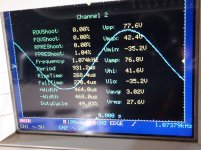
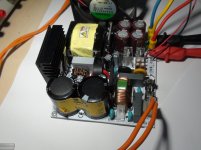
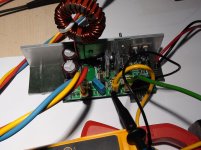
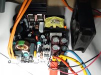
Today I finished my first PCB of the amplifier, I am showing a video of my setup, loading the amplifier 2 Ohms, 1Khz Sine wave, using my UNREGULATED SMPS to drive the amplifier.
I really like the performance of this amplifier.
Soon I will assemble the other PCB with for the +-80V version 😀
Some pictures and the video, ( the music was too loud in the video, sorry for that!)
https://www.youtube.com/watch?v=4T6JIH9cUzo
More Info
diysmps
I really like the performance of this amplifier.
Soon I will assemble the other PCB with for the +-80V version 😀
Some pictures and the video, ( the music was too loud in the video, sorry for that!)
https://www.youtube.com/watch?v=4T6JIH9cUzo
More Info
diysmps
Attachments

Last edited:
- Home
- Amplifiers
- Class D
- SystemD LiteAmp