

First measurements!
The horn is still missing the roundover for the top and bottom panels, but I just had to measure. I'll post some pics later.
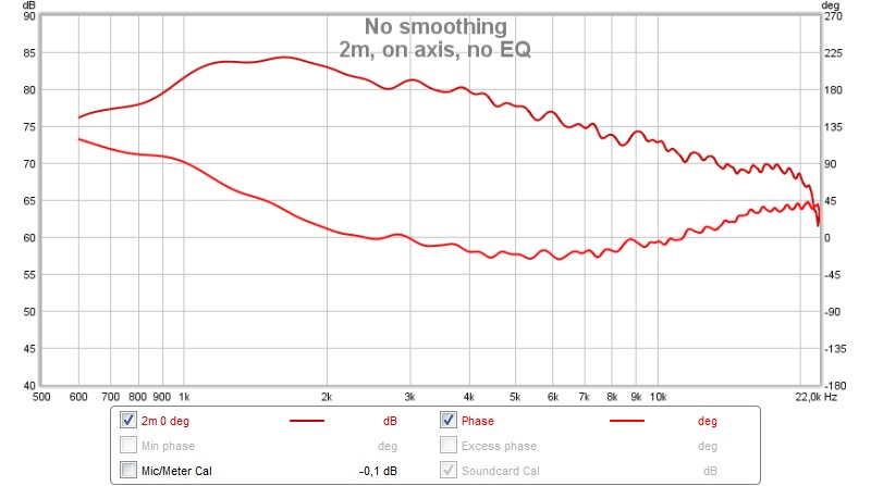
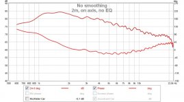
Raw on axis (2m):
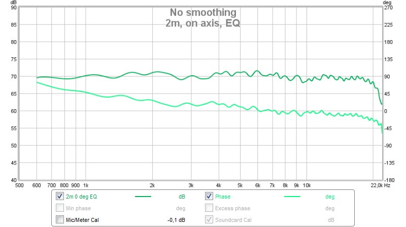
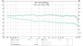
On axis with EQ (auto with REW+minidsp):
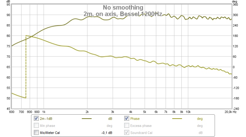
With Bessel LP at 1200 Hz:
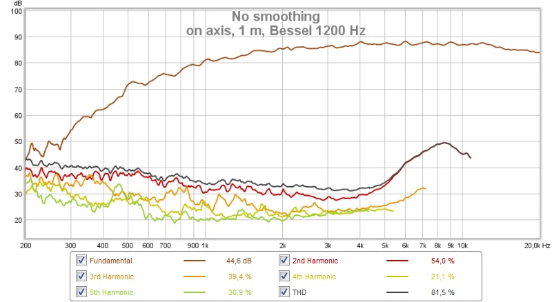
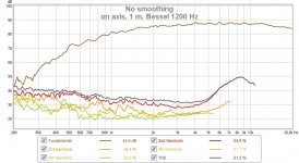
Distortion at 1 m distance (87 dB):
Distortion at 1 m distance (96 dB):
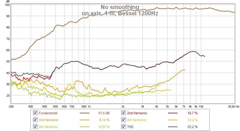
Better than with the small waveguide.
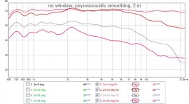
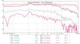
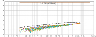
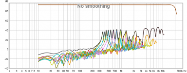
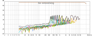
Horisontal polars at 2 m (0, 30, 60, 90 deg):
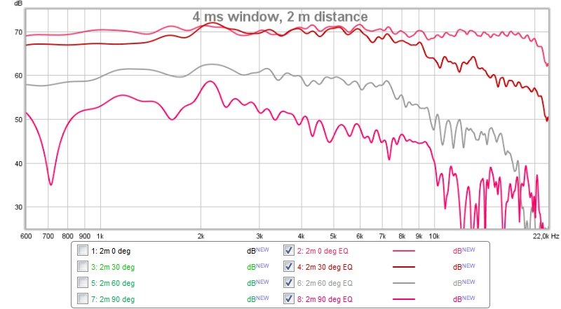
Same 4 ms window as before.
And here with no window, but psychoacoustic smoothing:
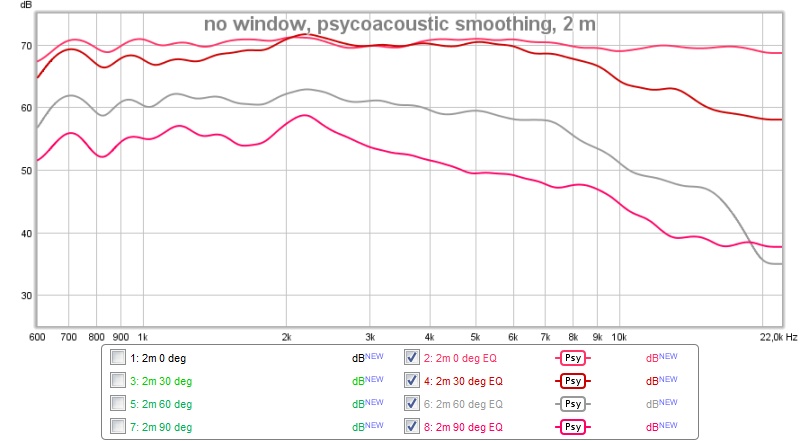
Not bad so far 🙂
/Anton
The horn is still missing the roundover for the top and bottom panels, but I just had to measure. I'll post some pics later.
Raw on axis (2m):
On axis with EQ (auto with REW+minidsp):
With Bessel LP at 1200 Hz:
Distortion at 1 m distance (87 dB):
Distortion at 1 m distance (96 dB):
Better than with the small waveguide.
Horisontal polars at 2 m (0, 30, 60, 90 deg):
Same 4 ms window as before.
And here with no window, but psychoacoustic smoothing:
Not bad so far 🙂
/Anton
Attachments
-
 2m, on axis, EQ, BS1200.jpg69 KB · Views: 555
 -
 2m, on axis, EQ.jpg70.4 KB · Views: 559
 -
 2m, on axis, no EQ.jpg74.6 KB · Views: 554
 -
 Horisontal, smoothing.jpg76.5 KB · Views: 857
 -
 Horisontal, windowed.jpg86.6 KB · Views: 562
 -
 1m, on axis, EQ, BS1200, 96dB.jpg83.6 KB · Views: 552
 -
 1m, on axis, EQ, BS1200, 87dB.jpg87.4 KB · Views: 554
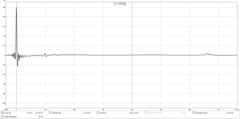
On axis with PEQ and LT.
Very interesting project, I'll follow your synergy development for sure!
Little critic: If you really want to see the actual driver response, you should avoid FIR filters (that's pretty obvious) for that kind of measurement. I'm not sure but that might actually have an influence on your distortion measurement. Just to rule it out, maybe try to change the filter type.
Using PEQ and Linkwitz Transform does not sound like using "FIR Filters" to me?
Care to explain that train of thought? I'm not getting it. 🙂
Care to explain that train of thought? I'm not getting it. 🙂
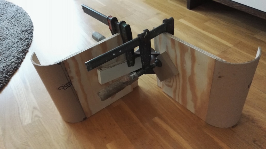
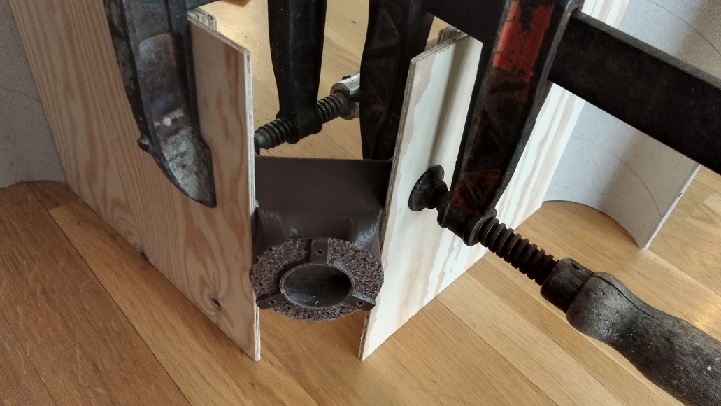
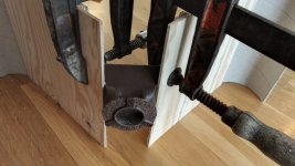
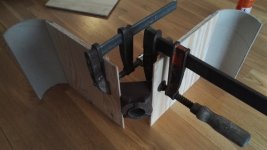
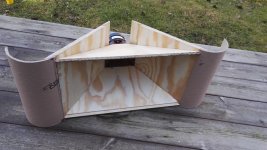
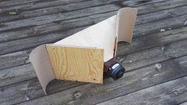
Thanks for all the encouraging words! Here's some photos and more measurements. I had some trouble with birds chirping, made all measurements at least twice :S
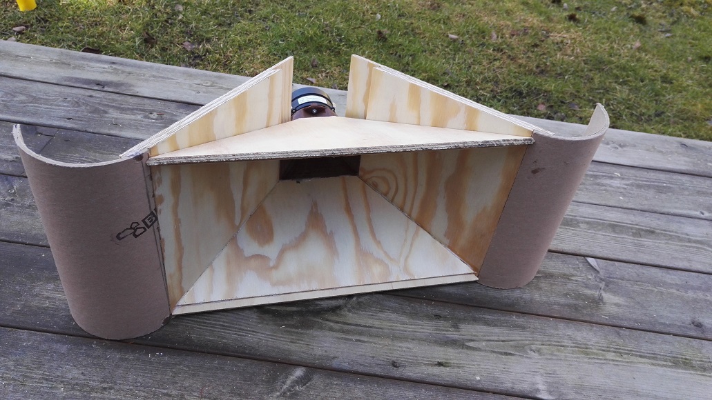
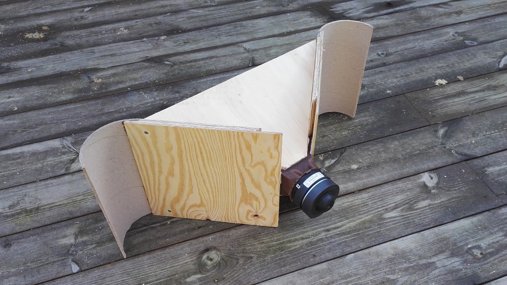
Still missing the top and bottom round over as you can see. It's all still very rough, glue blobs and seams without filler.
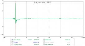
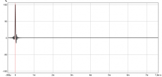
Impulse response with PEQ, no LP, at 2 m, on axis:
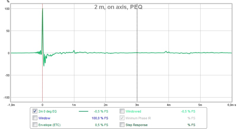
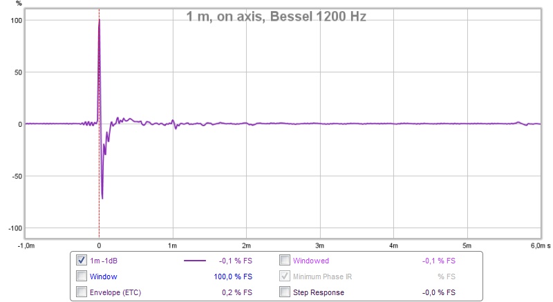
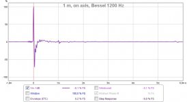
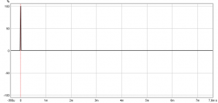
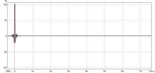
Impulse response with PEQ, Bessel LP 1200 Hz, at 1 m, on axis:
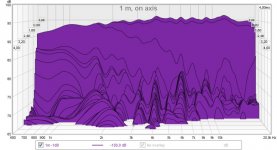
CSD with PEQ, Bessel LP 1200 Hz, at 1 m, on axis:

ICG: I'm only using IIR-filters like wesayso is saying.
wesayso: It'll be even better when I'll apply a little bit of Linkwitz Transform 🙂 Didn't have time for this fast measurement though. I expect similar results as in my first post.
/Anton
Still missing the top and bottom round over as you can see. It's all still very rough, glue blobs and seams without filler.
Impulse response with PEQ, no LP, at 2 m, on axis:
Impulse response with PEQ, Bessel LP 1200 Hz, at 1 m, on axis:
CSD with PEQ, Bessel LP 1200 Hz, at 1 m, on axis:
ICG: I'm only using IIR-filters like wesayso is saying.
wesayso: It'll be even better when I'll apply a little bit of Linkwitz Transform 🙂 Didn't have time for this fast measurement though. I expect similar results as in my first post.
/Anton
Attachments
Last edited:
ICG: I'm only using IIR-filters like wesayso is saying.
Using PEQ and Linkwitz Transform does not sound like using "FIR Filters" to me?
Care to explain that train of thought? I'm not getting it. 🙂
That's pretty clear pre-ringing in the impulse answer. You only get that with FIR-Filters, IIR Filters lack that typical FIR-characteristics.
That could just as easily be the signal chain causing that ripple. I could generate a FIR filter to get rid of it though 🙂.
A loopback of the Dac to the line in could show it..
A loopback of the Dac to the line in could show it..
That could just as easily be the signal chain causing that ripple. I could generate a FIR filter to get rid of it though 🙂.
A loopback of the Dac to the line in could show it..
Well, that kind of ripple could explain the distortion increase too. It's not always the speaker which introduces a divergence in the signal. I might be wrong but if you encounter something odd, you'd want to optimize or recheck your signal chain even if it's only to rule it out. I think it's worth to try that out before you blame your design or the drivers.
The signal chain in this case is pretty crappy: laptop->$10 USB DAC (not shielded)->minidsp (cheapest one)->$10 Tpa3116 amp (not shielded). Long cables in a mess as well...That could as easily be the signal chain causing that ripple. I could generate a FIR filter to get rid of it though 🙂.
Final signal chain will be: computer->nanoavr HDA->anaview alc0100. Hopefully a lot better.
/Anton
Interesting point, I had to set the volume of the DAC to 100 % to make the 96 dB measurement. I'll try with a different set of DACs and amps when I have time.Well, that kind of ripple could explain the distortion increase too. It's not always the speaker which introduces a divergence in the signal. I might be wrong but if you encounter something odd, you'd want to optimize or recheck your signal chain even if it's only to rule it out. I think it's worth to try that out before you blame your design or the drivers.
/Anton
To me it seems it could be a mismatch in sample rate somewhere in the chain.
Try and make sure every driver setting has the same sample rate set. But there are many possible reasons. Some drivers are only optimized at one specific sample rate. Nowadays that probably is 48000.
Another cause can be Asio buffers... I agree that it's best to optimize it. A loop back can show you where you stand.
Last edited:
SR mismatch as wesayso point to could be reason, here is real world example running mismatch with soundcard AP192 using its SPDIF I/O as loopback.
In first plot WDM drivers and REW is in synch at 44,1kHz, in second plot WDM is still at 44,1kHz but REW run 48kHz, in third plot WDM run 48kHz and REW 44,1kHz.
Pre ringing scheme in third plot reminds the one in post 1.
In first plot WDM drivers and REW is in synch at 44,1kHz, in second plot WDM is still at 44,1kHz but REW run 48kHz, in third plot WDM run 48kHz and REW 44,1kHz.
Pre ringing scheme in third plot reminds the one in post 1.
Attachments
I was hoping you would chime in with some examples, BYRTT, thanks.
Despite the ripple it can still give a flat frequency plot from 20 Hz to 20 kHz.
Despite the ripple it can still give a flat frequency plot from 20 Hz to 20 kHz.
Yes frq is still flat despite the ripple in IR/SR, as can be seen in below distortion plots, but other figures get worse.
Same scheme as previous post, WDM driver at 44,1kHz together with REW, then WDM at 44,1kHz but REW at 48kHz, and last WDM at 48kHz but REW at 44,1kHz.
Same scheme as previous post, WDM driver at 44,1kHz together with REW, then WDM at 44,1kHz but REW at 48kHz, and last WDM at 48kHz but REW at 44,1kHz.
Attachments
Last edited:
- Home
- Loudspeakers
- Multi-Way
- Synergy attempt without compression driver