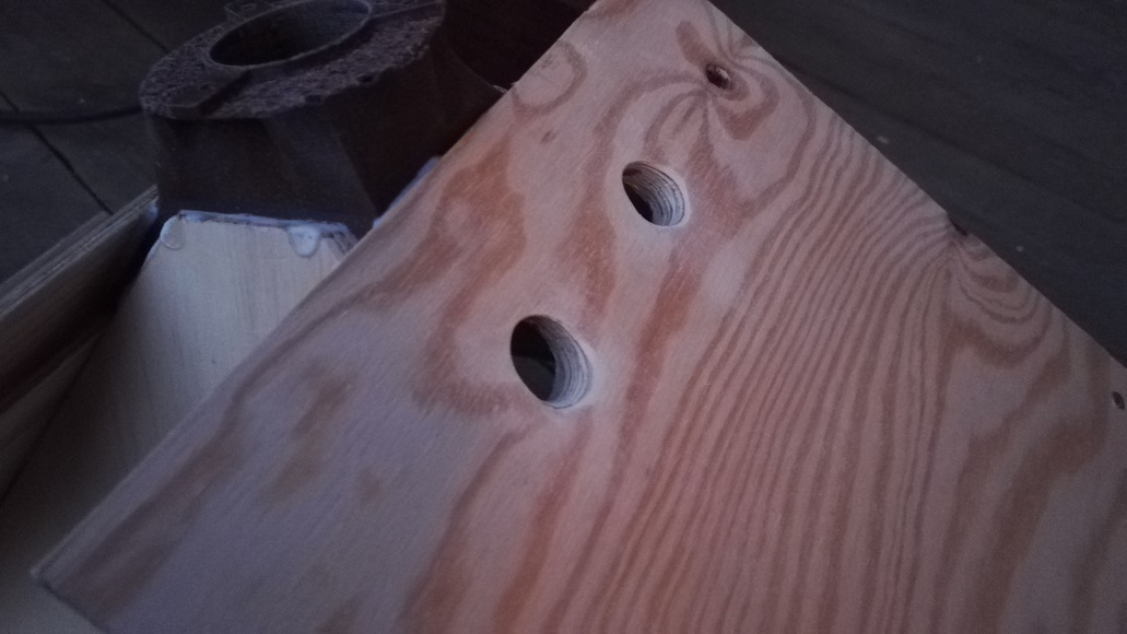
1 set of BP-holes made
Some progress made today: The horn has all roundovers and is now smoother after a round of wood filler and sanding:
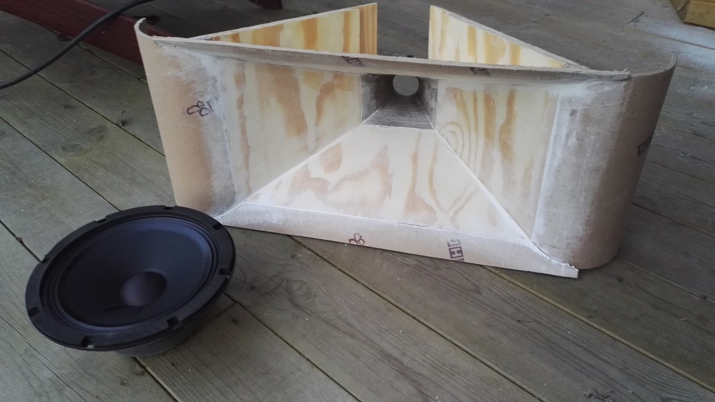
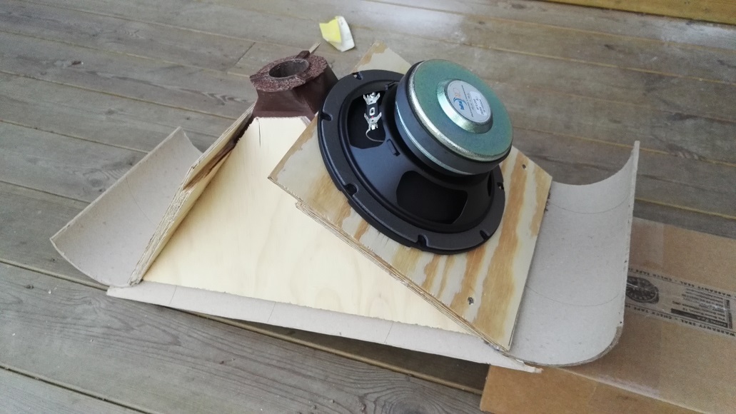
Test fitting the 8FE200:
BP-holes made with a 18 mm drill but oblique angle, so should be area ~20 mm drill:
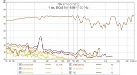
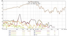
I measured the woofer response out of curiosity, even though there is no volume filler or box:
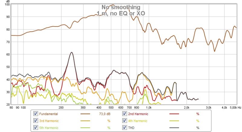
Raw measurement at 1 m.
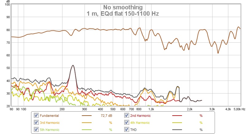
EQd flat.
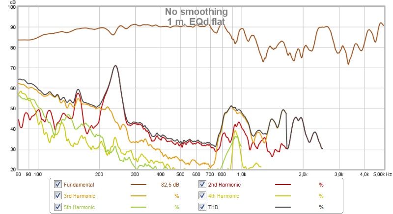
Same, but higher level. There seems to be a resonance at 240 Hz, probably some part of the horn as it has no damping and quite a few free edges.
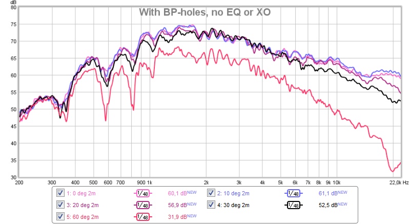
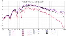
I made some new measurements of the R2604 to see effect of BP-holes. First raw (no EQ, XO, smoothing or gating) at 0, 10, 20, 30 and 60 deg:
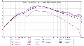
And the same measurement with a 5 ms window:

Maybe I should EQ for 30 deg as it is very smooth already without any correction.
After these measurements I added some wood filler to make the BP-holes smoother (there were some splinters from the drill).
Next step is to produce a volume filler, I'm guessing that 3D-printing is the easiest path as I have access to that. Does anyone have any pointers here? Should I just fill as much as possible without making the BP-holes longer?
/Anton
Some progress made today: The horn has all roundovers and is now smoother after a round of wood filler and sanding:
Test fitting the 8FE200:
BP-holes made with a 18 mm drill but oblique angle, so should be area ~20 mm drill:
I measured the woofer response out of curiosity, even though there is no volume filler or box:
Raw measurement at 1 m.
EQd flat.
Same, but higher level. There seems to be a resonance at 240 Hz, probably some part of the horn as it has no damping and quite a few free edges.
I made some new measurements of the R2604 to see effect of BP-holes. First raw (no EQ, XO, smoothing or gating) at 0, 10, 20, 30 and 60 deg:
And the same measurement with a 5 ms window:
Maybe I should EQ for 30 deg as it is very smooth already without any correction.
After these measurements I added some wood filler to make the BP-holes smoother (there were some splinters from the drill).
Next step is to produce a volume filler, I'm guessing that 3D-printing is the easiest path as I have access to that. Does anyone have any pointers here? Should I just fill as much as possible without making the BP-holes longer?
/Anton
Attachments
-
 IMG_20160410_194946.jpg162.3 KB · Views: 1,043
 -
 IMG_20160410_194643.jpg168.7 KB · Views: 651
 -
 IMG_20160410_202614.jpg137.3 KB · Views: 651
 -
 r2604 with bp-holes, windowed.jpg82.1 KB · Views: 646
 -
 r2604 with bp-holes.jpg93.3 KB · Views: 644
 -
 8fe200, EQ, 90 dB.jpg90.6 KB · Views: 633
 -
 8fe200, EQ.jpg86 KB · Views: 646
 -
 8fe200, no EQ or XO.jpg88.7 KB · Views: 647
Last edited:
Anton,
Nice progress, have you tried to use hornresp to give you an idea of how much front volume you need to aim for?
Do you plan to route a clearance ring or use a spacer to make sure the surround of the woofer can't touch the horn wall, this could have something to do with the distortion spike at 240Hz.
Nice to see that the horn seems to control the directivity so that the off axis is a lot smoother compared to flat baffle:

I'm assuming that it's 0, 30 and 60 deg.
Yup, I'm routing a clearance ring.
/Anton
I'm assuming that it's 0, 30 and 60 deg.
There are hornresp sims on first page of this thread, I need to get the volume below 200 ml for each woofer.Anton,
Nice progress, have you tried to use hornresp to give you an idea of how much front volume you need to aim for?
Do you plan to route a clearance ring or use a spacer to make sure the surround of the woofer can't touch the horn wall, this could have something to do with the distortion spike at 240Hz.
Yup, I'm routing a clearance ring.
/Anton
Last edited:
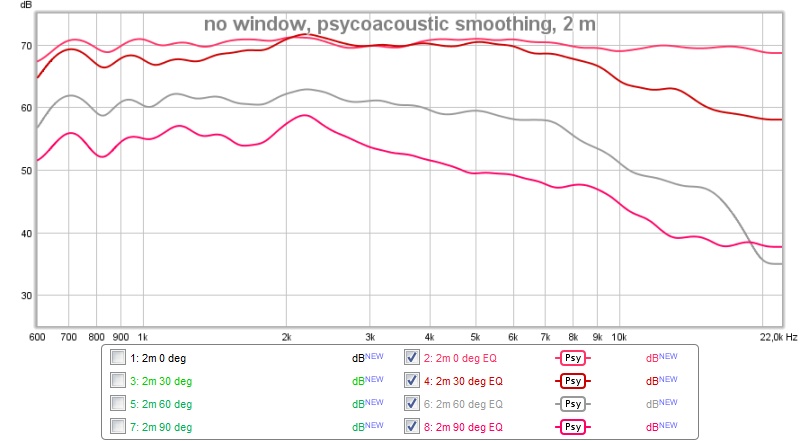
I started wondering why the BP-holes seemed to have no effect on the response when looking at the figures from yesterday. So I measured again, now with the 10 uF capacitor and PEQ:
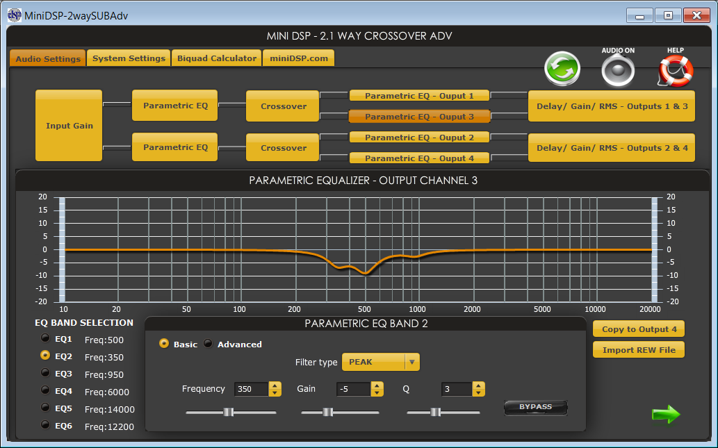
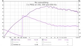
Only used to shape response below 1 kHz at 15 deg to Bessel (2 m distance):
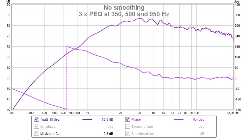
Very smooth!
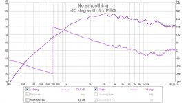
But how about at -15 deg?
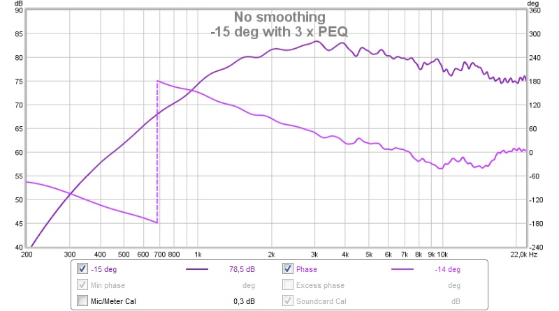
That's more expected.
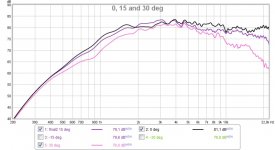
Here's 0, 15, 30 deg (same side as BP-holes):
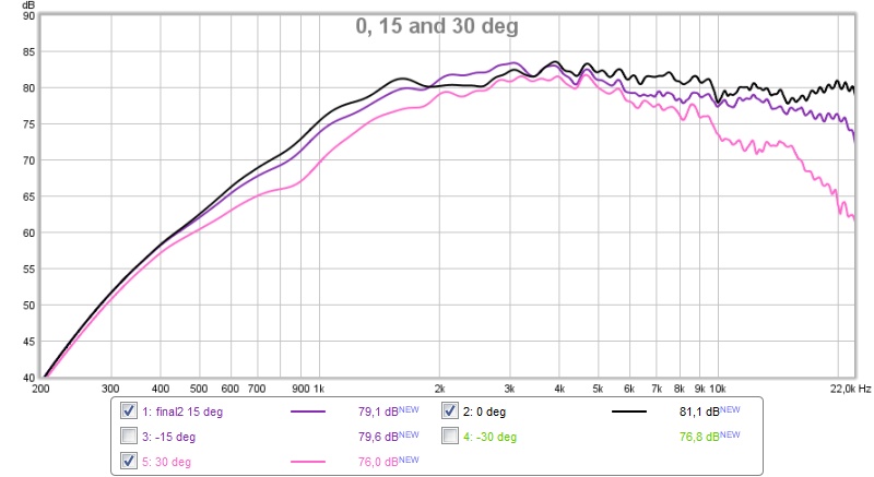
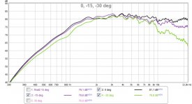
And 0, -15, -30 deg:
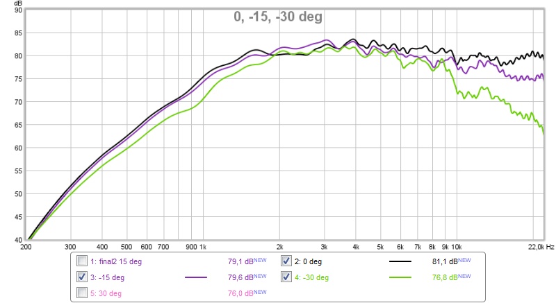
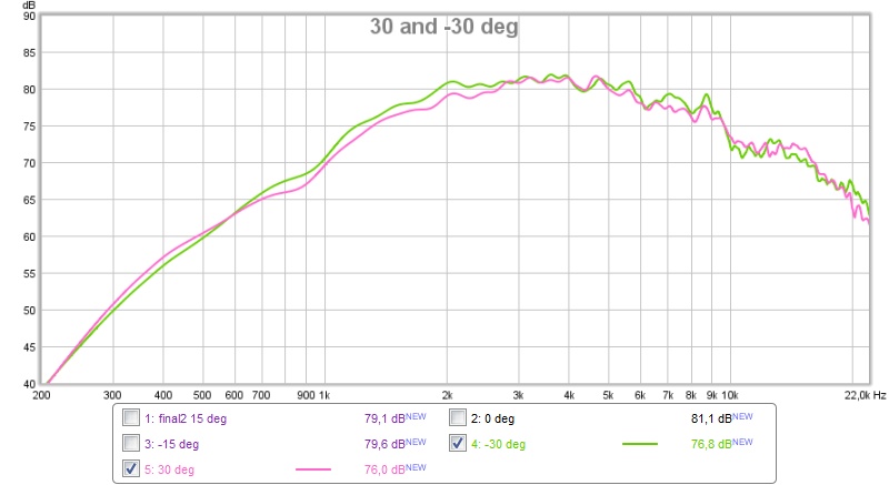
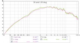
Comparison of -30 and 30:
/Anton
Only used to shape response below 1 kHz at 15 deg to Bessel (2 m distance):
Very smooth!
But how about at -15 deg?
That's more expected.
Here's 0, 15, 30 deg (same side as BP-holes):
And 0, -15, -30 deg:
Comparison of -30 and 30:
/Anton
Attachments

So far so good! Nice progress. Any plans to dampen the horn itself?
What are your plans for the back chamber of the mids? Build the enclosure like the designs shown earlier and some braces? How much volume do the mids need?
It will be interesting to see what adding the second mid does for the distortion figures.
What are your plans for the back chamber of the mids? Build the enclosure like the designs shown earlier and some braces? How much volume do the mids need?
It will be interesting to see what adding the second mid does for the distortion figures.
I'm experimenting with a flexible acrylic adhesive to use as CLD (Constrained Layer Damping), seems very effective on small test pieces.So far so good! Nice progress. Any plans to dampen the horn itself?
What are your plans for the back chamber of the mids? Build the enclosure like the designs shown earlier and some braces? How much volume do the mids need?
It will be interesting to see what adding the second mid does for the distortion figures.
The plan for the back chamber is to use what I've learned in this thread: http://www.diyaudio.com/forums/multi-way/281789-leaky-supercardioid-mids.html
I.e make a lot of holes and then fill the cavity with absorptive material. Here's a polar (0, 45, 90, 135, 180) for the mids from that thread:
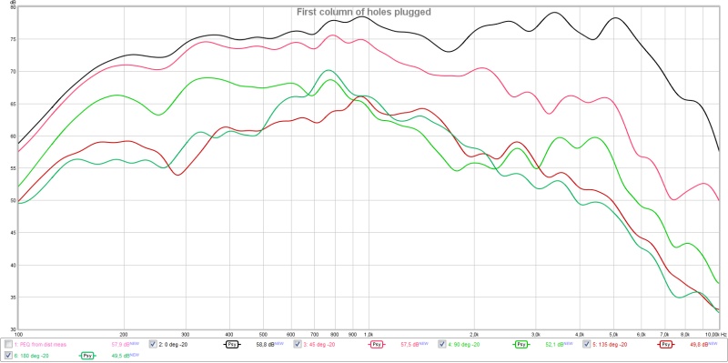
12 dB separation at 90 deg, 1.2 kHz (intended XO). Compared to the polar for the R2604 in the horn from earlier in this thread:
13 dB separation at 90 deg, 1.2 kHz. Looks like it could fit well, but the geometry for the mids is drastically different, so the behavior could also differ a lot.
Well, no... I'm trying to build a compact (on top of media console) two-way point source horn with ~constant directivity 150 Hz - 20 kHz using a ringradiator (ScanSpeak R2604/833000) and two 8" mids/woofers (Faital Pro 8FE200) inspired by Danley Sound Labs Synergy speakers (Link).I'm trying to figure this out - you are building a 90 db sensitive horn?
Main difference is that I'm not using a compression driver (like Danley) but a ringradiator as tweeter. I'm sacrificing loudness (>100 dB) and sensitivity for weight/size/better CSD.
I'm not that concerned with sensitivity as I'm mainly using the miniDSP NanoAVR for XO and PEQ.
/Anton
I just look at this as a clever way to do a MTM with close spacing and superior polar behavior. Should be interesting to see the cardoid mids in something like this.
Based on my own experience I would be tempted to use butyl rope between the horn and an extra layer for damping to create the CLD. It is sold for automotive purposes to seal windshields, lights etc.

It's close to the same compound used on a lot of brands of car damping sheets. It remains flexible and is easy to work with.
Based on my own experience I would be tempted to use butyl rope between the horn and an extra layer for damping to create the CLD. It is sold for automotive purposes to seal windshields, lights etc.
It's close to the same compound used on a lot of brands of car damping sheets. It remains flexible and is easy to work with.
Attachments
Good suggestion! I see that It's available as wide stripes (50 mm) that should make application easy.I just look at this as a clever way to do a MTM with close spacing and superior polar behavior. Should be interesting to see the cardoid mids in something like this.
Based on my own experience I would be tempted to use butyl rope between the horn and an extra layer for damping to create the CLD. It is sold for automotive purposes to seal windshields, lights etc.
It's close to the same compound used on a lot of brands of car damping sheets. It remains flexible and is easy to work with.
/Anton
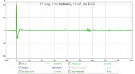
A small experiment
I did a small experiment today to see where the pre-ringing originates from. Using the internal soundcard in the laptop instead of the external (cheap) DAC had no effect, but removing the miniDSP did:
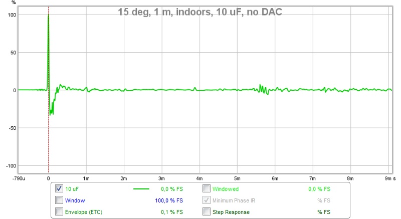
"no DAC" should be "no miniDSP" in the pic.
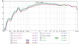
I did also test a few values of capacitor:
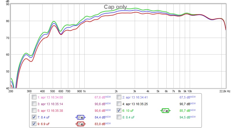
10 uF, 8.4 uF (4.7 + 2.2 + 1.5 uF) and 6.9 uF (4.7 + 2.2 uF).
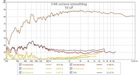
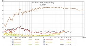
Distortion:


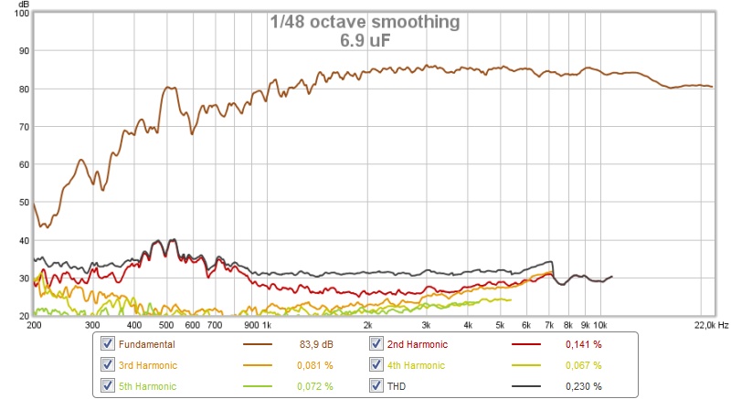
All measurements indoors at 1 m, about 15 deg off axis. It was primarily a test to see if a simple first order XO would be enough to control distortion, it's not. A cap + a notch would probably be fine, but a notch at 500 Hz is typically expensive components.
/Anton
I did a small experiment today to see where the pre-ringing originates from. Using the internal soundcard in the laptop instead of the external (cheap) DAC had no effect, but removing the miniDSP did:
"no DAC" should be "no miniDSP" in the pic.
I did also test a few values of capacitor:
10 uF, 8.4 uF (4.7 + 2.2 + 1.5 uF) and 6.9 uF (4.7 + 2.2 uF).
Distortion:
All measurements indoors at 1 m, about 15 deg off axis. It was primarily a test to see if a simple first order XO would be enough to control distortion, it's not. A cap + a notch would probably be fine, but a notch at 500 Hz is typically expensive components.
/Anton
Attachments

Last edited:
Looks also post ringing in area below 0,2mS decreased, was that your NanoAVR bypassed or other miniDSP model.
Thanks link other day woofer thread (http://www.diyaudio.com/forums/multi-way/281789-leaky-supercardioid-mids.html) great stuff in there.
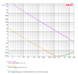
Know capasitor have many good reasons to sit there but decrease a possible low Z route to amp if system down the road would benefit that, purple below is live measurement of 10uF and for fun did throw in some other extremes.
Thanks link other day woofer thread (http://www.diyaudio.com/forums/multi-way/281789-leaky-supercardioid-mids.html) great stuff in there.
Know capasitor have many good reasons to sit there but decrease a possible low Z route to amp if system down the road would benefit that, purple below is live measurement of 10uF and for fun did throw in some other extremes.
Attachments
I just look at this as a clever way to do a MTM with close spacing and superior polar behavior. Should be interesting to see the cardoid mids in something like this.
Based on my own experience I would be tempted to use butyl rope between the horn and an extra layer for damping to create the CLD. It is sold for automotive purposes to seal windshields, lights etc.
It's close to the same compound used on a lot of brands of car damping sheets. It remains flexible and is easy to work with.
Parts Express used to throw this in for free with every order.
I use a TON of mortite in my projects. Readily available in the weatherproofing department of home depot.
Thanks for following the process and providing input! 🙂Thank you for doing the research and posting the measurements!
I'm only doing measurements, no listening to music. I do however clearly hear that without PEQ around 500 Hz there is significant distortion in first part of sweep.Onni, can you hear the pre-ringing?
Peter
If I look at the re-ringing it has a period of 40 us, that is a frequency of 25 kHz.
It was the miniDSP 2x4 (here). I'll do a new test with the nanoAVR later, it should be an improvement as it skips one ADC/DAC step (takes digital audio from HDMI and can be 96 kHz from start to finish) and has a better DSP.Looks also post ringing in area below 0,2mS decreased, was that your NanoAVR bypassed or other miniDSP model.
Thanks link other day woofer thread (http://www.diyaudio.com/forums/multi-way/281789-leaky-supercardioid-mids.html) great stuff in there.
Know capasitor have many good reasons to sit there but decrease a possible low Z route to amp if system down the road would benefit that, purple below is live measurement of 10uF and for fun did throw in some other extremes.
The ringing below 0.2 ms probably decreased from earlier measurements due to added roundovers and wood filler. Here is a direct comparison of measurement with miniDSP 2x4 and without:
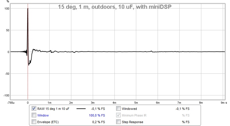
With.
Without. Only difference is that one is measured outdoors and one indoors.
I'm not that familiar with impedance measurements. Why would I want a low impedance load?
/Anton
Attachments
Thanks showing direct comparison, traces i rated is wrong then and not comparable.
That miniDSP 2x4 version is available as bare PCB too and included in many many shared build measurements, any chance if internal sensitivity jumpers could change anything (RC filter value) or miniDSP support have a firmware upgrade that is not public available without personal request owing the hardware, or it could be differences in the seven different plugins they offer, or differences in released PCB hardware versions.
In reality don't know if you need the low impedance route its just thoughts after reading info about possible LF acoustic pressure modulation of tweeter from close range midwoofer ports. Somewhere seen mentioned that some passive designs by Tom Danley have a inductor direct across tweeter terminals to make a short that stiffen and make a electric brake for voice coil. If there is something about this subject in your build at all is not to know, a little test further down the road under higher spl and with and without a low impedance amp direct connected think would reveal in measurements.
Last edited:
That pre-ring sometimes comes from the top end HF low pass at 20kHz. I have done the with and without miniDSP and find it is quite transparent (does not affect signal from basis of DAC alone) as long as you make sure all filters are off. In any case, I can't hear that pre-ring - it's at a very low amplitude.
Got to think about xrk971 info that if one use analog mic it should be possible calibrate REW to be ringing free by a loop including soundcard/miniDSP(DSP filters off)/micPreamp/soundcard, in that correction file that loop would correct for all analog/digital filters and mic has its own so in measurements we see only real DUT measurement data. If its possible later find out soundcards input stand alone correction and extract it on math in "All SPL" tab from before made loop correction file and also take mic preamp out of that loop then a USB mic can be added afterwards. It wont help when going back to normal system playback where the various filters signature will be back into sound stream but think should help isolate measurement data to plot only DUT. Last step for flexibility and precision is then to do those correction files for all intended driver modes WDM/ASIO and the various sample rates.
Had a look into REW how a imported 44,1kHz 2nd order low pass filter as BW2 plus BS2 and also both as IRR and FIR filters looks like. Think not these 2nd order tests ring much compared some of the real world loop data we see so maybe ADC part of our chains is worse part to ring than DAC part.
Had a look into REW how a imported 44,1kHz 2nd order low pass filter as BW2 plus BS2 and also both as IRR and FIR filters looks like. Think not these 2nd order tests ring much compared some of the real world loop data we see so maybe ADC part of our chains is worse part to ring than DAC part.
Last edited:
Why not do a loopback of the miniDSP->Dac back into the line in and measure a REW sweep. It will probably show where that ringing is if we look in the right places. While the above might work to counter the pre-ringing, you'd still have it when playing music.
- Home
- Loudspeakers
- Multi-Way
- Synergy attempt without compression driver