Butyl rope/band
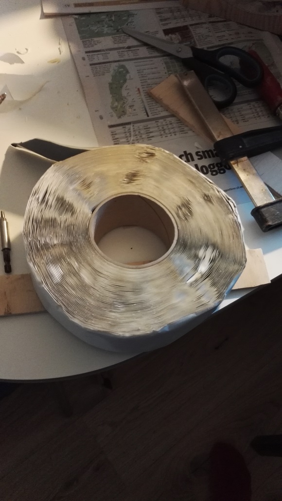
I bought some butyl band today, it's 50 mm wide (2") and 1 mm thick. It's a new product for me, feels like "häftmassa" (Blu-tack, Tack-it) but a little more sticky:
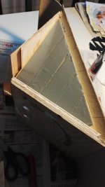
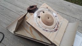
I added a layer on the top and bottom panel as they are largest:

On top of this I added another 11 mm plywood panel (scrap piece) and clamped it for 15 mins. I also added a small (40 mm wide) beam on the side panels beside the woofer with butyl band. As you can see on the picture above I've started with some routing and I have a simple volume filler made of MDF done. Hopefully I'll be able to do the last routing and mount tomorrow.
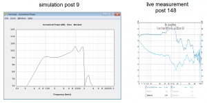
About the pre-ringing. It's at 25 kHz, my hearing does not come even close to that. So it's a cosmetic thing in the plots, but it would be nice to get rid of it. Someday I'll do a measurement with the nanoAVR to see if it shows the same phenomenon.
/Anton
I bought some butyl band today, it's 50 mm wide (2") and 1 mm thick. It's a new product for me, feels like "häftmassa" (Blu-tack, Tack-it) but a little more sticky:
I added a layer on the top and bottom panel as they are largest:
On top of this I added another 11 mm plywood panel (scrap piece) and clamped it for 15 mins. I also added a small (40 mm wide) beam on the side panels beside the woofer with butyl band. As you can see on the picture above I've started with some routing and I have a simple volume filler made of MDF done. Hopefully I'll be able to do the last routing and mount tomorrow.
About the pre-ringing. It's at 25 kHz, my hearing does not come even close to that. So it's a cosmetic thing in the plots, but it would be nice to get rid of it. Someday I'll do a measurement with the nanoAVR to see if it shows the same phenomenon.
/Anton
Attachments

From what I know about the automotive products they have varying thicknesses of the butyl layer from ~2 mm up to 4 mm or more. Experimentation might be in order 🙂.
I hope it works for you. I kinda feel a bit responsible now 😉.
I hope it works for you. I kinda feel a bit responsible now 😉.
I read in some paper about CLD that the thickness of the viscous layer only had a small effect on the damping properties. Adding a lot of butyl increases the weight of the panel and thereby lowers the first eigenfrequency. But it would be easy to just add 2 layers of the butyl band instead of one, as you say, some experimentation might be in order.From what I know about the automotive products they have varying thicknesses of the butyl layer from ~2 mm up to 4 mm or more. Experimentation might be in order 🙂.
I hope it works for you. I kinda feel a bit responsible now 😉.
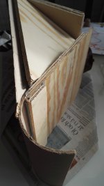
This is what the extra beam for the side panel looks like:

I tried the traditional "knocking test" and the sound is drastically different from before the treatment. I have however increased the amount of plywood by ~30 % so that is maybe not very unexpected. But there is almost no ringing, it doesn't really sound like I'm knocking on wood. 🙂
/Anton
Attachments
I'd say beside the added weight, increasing the distance between both outer layers will make a difference for bending modes. Easy enough to try I guess.
A few measurements
Still no box, only some fabric covering the back.
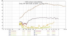
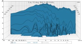
First a new measurement of the R2604 with only a 6 dB BW at 6 kHz (no cap), at 1 m, 15 deg:
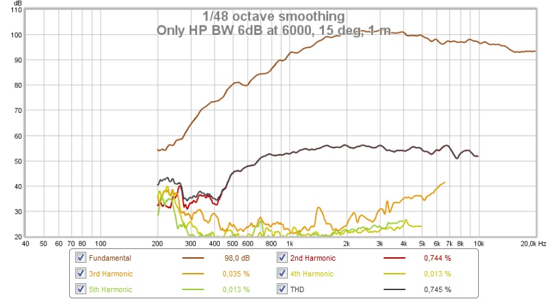
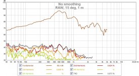
It seems like the distortion around 500 Hz was due to panel vibrations!
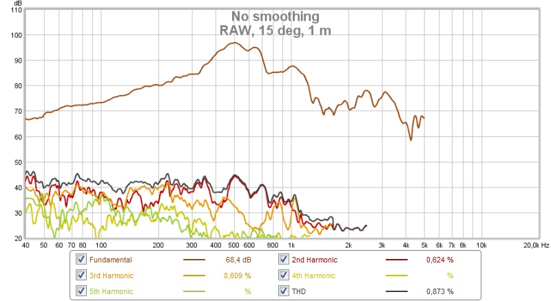
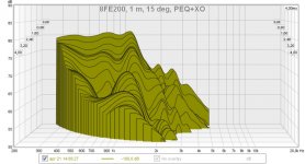
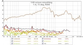
Raw measurement of 8FE200 at same position:
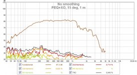
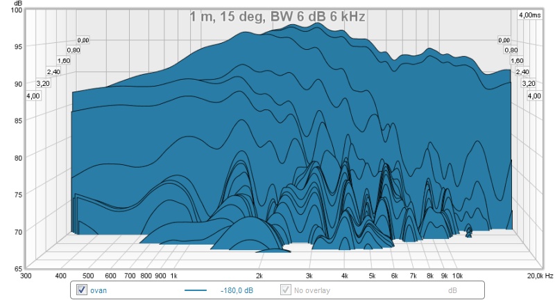
and with PEQ and XO:

When I exceed 85 dB the distortion starts rising and at around 89 dB there is some obvious scraping (cone against volume filler I think).
/Anton
Still no box, only some fabric covering the back.
First a new measurement of the R2604 with only a 6 dB BW at 6 kHz (no cap), at 1 m, 15 deg:
It seems like the distortion around 500 Hz was due to panel vibrations!
Raw measurement of 8FE200 at same position:
and with PEQ and XO:
When I exceed 85 dB the distortion starts rising and at around 89 dB there is some obvious scraping (cone against volume filler I think).
/Anton
Attachments


Nice work Onni. When I look at this photo, I finally get an idea of the relative size of the band pass injection holes relative to the driver Sd. It appears a bit small. Have you calculated the velocity through those ports at your max SPL? I try to keep below 15 m/s, 20 m/s tops.
For CLD or panel damping, I use latex/silicone blend (household bath/kitchen) caulking. You can add sand to it to increase mass. It bonds the two panels together and stays flexible - it doesn't have to have 100% coverage - I use maybe 30% coverage - but the difference in sound from the knuckle rap test is noticeably different. A dull thud vs a sharp ring.
http://www.homedepot.com/p/DAP-Alex...lic-Latex-Caulk-Plus-Silicone-18103/100097524
Fairly low cost and useful as airtight sealant for cabinets too.
Last edited:
The holes are indeed quite small, I want them to affect the tweeter performance as little as possible (as they are close). I'm not sure how to calculate port velocity for the supercardioid case... For a closed case I did sims here with slightly larger holes. But I'm actually only aiming for a XO at 150 Hz which should make it below the Schröder-frequency in my living room. Controlled directivity is more important from that point and up.Nice work Onni. When I look at this photo, I finally get an idea of the relative size of the band pass injection holes relative to the driver Sd. It appears a bit small. Have you calculated the velocity through those ports at your max SPL? I try to keep below 15 m/s, 20 m/s tops.
For CLD or panel damping, I use latex/silicone blend (household bath/kitchen) caulking. You can add sand to it to increase mass. It bonds the two panels together and stays flexible - it doesn't have to have 100% coverage - I use maybe 30% coverage - but the difference in sound from the knuckle rap test is noticeably different. A dull thud vs a sharp ring.
DAP Alex Plus 10.1 oz. White Acrylic Latex Caulk Plus Silicone-18103 - The Home Depot
Fairly low cost and useful as airtight sealant for cabinets too.
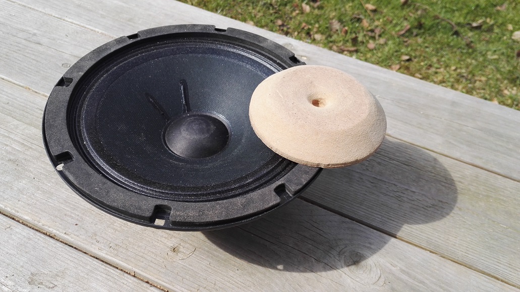
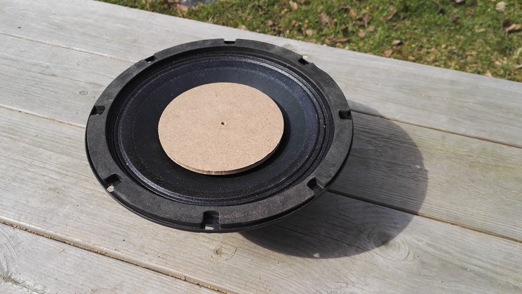
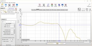
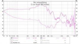
Here is the woofer response 5 cm from the BP-holes:
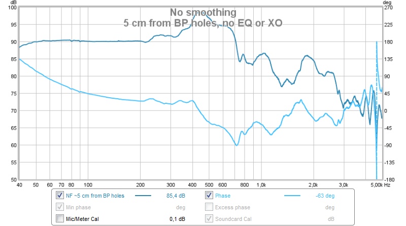
I'm really hoping that making a box to increase the distance between the front and back wave will have some effect on the response. It falls of with a textbook 6 db/octave from 350 Hz at 1 m now which requires a lot of EQ.
/Anton
Attachments
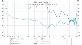
Well, the phase plug only works properly if it's loading into a symmetrical-to-the-driver horn. Otherwise you'll alway have again the same problems with the phase (or, if you want, run-time) differences. So no, to increase the distance between the front and back wave will not have the desired effect. At least not in the problematic frequency range. I have more the impression, your small holes work probably more as a helmholtz resonator. To verify you could also look at the waterfall or impedance diagram.
Here in the states, I use roofing membrane and fibrous roofing cement for CLD as both products are relatively easy to find and cost effective. Only drawback is the cement gasses off for a few days so build time is extended.
When you say phase plug I assume you refer to the volume filler? The reason I added it is to move the LP point of the chamber between the cone and horn wall up. But sure, it acts like a phase plug, and the size of the driver may be what causes the irregularities around 400-700 Hz. The sharp dip around 900 Hz was at least removed by the volume filler.Well, the phase plug only works properly if it's loading into a symmetrical-to-the-driver horn. Otherwise you'll alway have again the same problems with the phase (or, if you want, run-time) differences. So no, to increase the distance between the front and back wave will not have the desired effect. At least not in the problematic frequency range. I have more the impression, your small holes work probably more as a helmholtz resonator. To verify you could also look at the waterfall or impedance diagram.
Here are the CSD-measurements:
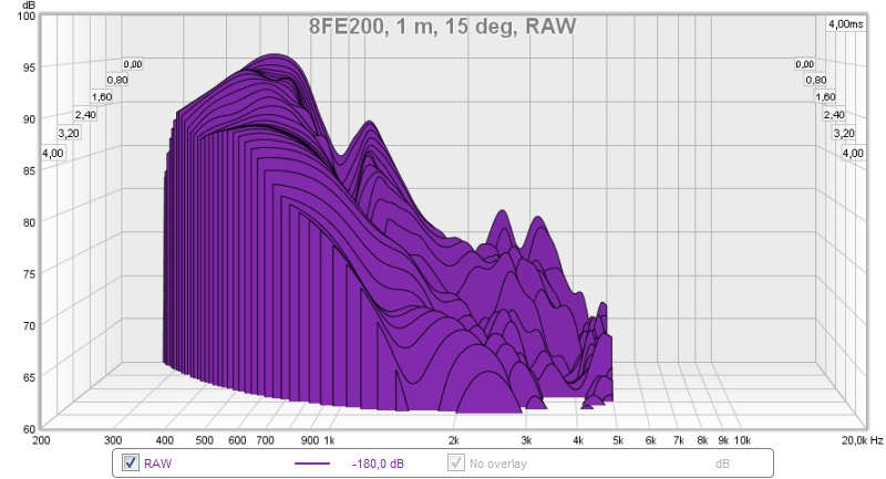
From raw 8FE200 measurement.

With PEQ and XO.
For the R2604 with BW 6 dB at 6 kHz.
I'm thinking there is a problem right now that the back wave arrive before the front wave as parts of the cone backside is closer to the mic than the BP-holes, at least when off-axis.
Here is a polar measurement I did after making a quick XO that looked decent at 15 deg:
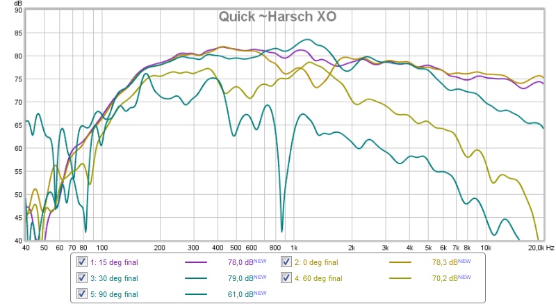
Quite heavy irregularities around the XO (1.2 kHz).
/Anton
Attachments


Tweeter!
The more i see of that tweeter the more impressed i become.
Have you tought about dropping the synnergi and just use the horn With the woofers in the horn? If you understand How i mean?
The more i see of that tweeter the more impressed i become.
Have you tought about dropping the synnergi and just use the horn With the woofers in the horn? If you understand How i mean?
my results with a top hat phase plug
Hi Onni;
I spent some time contending with the 8FE200 for a synergy and had to deal with the limited high end bandwidth due, I concluded, to the size of the driver. I eventually made what I called a tophat phase plug. It was hollowed out with tunnels to the BP holes in the horn wall. Sound entered it in the center just under the top hat and then exited out bandpass holes near the edges of the driver. This extended the BW out to 1200 hz, avoiding or delaying the onset of cancellation from the most distant parts of the cone. The measured FR with a 4 cycle FDW looked quite smooth. I was aiming for a 1 Khz crossover so I didn't try to go higher. Clearly, the tunnels through the phase plug can be optimized. I simply made them as large as I could and was satisfied with what I got.
I eventually gave up on the 8FE200 because I didn't have enough room in my box to absorb the back wave and couldn't make it deeper without starting over. Open back the response was fine. Closed up and sealed, I had a cancellation null around 900 Hz which corresponded to the depth of my box.
Jack
Attachments
What would be the benefit to that? I'd guess you'd have a worse response from the tweeter with the woofer cones exposed in the wg, and you'd be eliminating the bp chamber and the benefits that brings to the table.The more i see of that tweeter the more impressed i become.
Have you tought about dropping the synnergi and just use the horn With the woofers in the horn? If you understand How i mean?
My thougths are that it would make the woofer inte some kind of ob. As i see it would ut make it easier to "fix" the woofers. But i am sure your right about the tweeter.
I'm also very impressed with the R2604!The more i see of that tweeter the more impressed i become.
Have you tought about dropping the synnergi and just use the horn With the woofers in the horn? If you understand How i mean?
Thanks for the info, I agree that this seems to be the main problem with an 8" driver as mid in a synergy type arrangement. I've done some experimenting today and will post measurements 🙂Hi Onni;
I spent some time contending with the 8FE200 for a synergy and had to deal with the limited high end bandwidth due, I concluded, to the size of the driver. I eventually made what I called a tophat phase plug. It was hollowed out with tunnels to the BP holes in the horn wall. Sound entered it in the center just under the top hat and then exited out bandpass holes near the edges of the driver. This extended the BW out to 1200 hz, avoiding or delaying the onset of cancellation from the most distant parts of the cone. The measured FR with a 4 cycle FDW looked quite smooth. I was aiming for a 1 Khz crossover so I didn't try to go higher. Clearly, the tunnels through the phase plug can be optimized. I simply made them as large as I could and was satisfied with what I got.
I eventually gave up on the 8FE200 because I didn't have enough room in my box to absorb the back wave and couldn't make it deeper without starting over. Open back the response was fine. Closed up and sealed, I had a cancellation null around 900 Hz which corresponded to the depth of my box.
Jack
/Anton
More R2604 experiments
The distortion when only applying a HP filter (at 6 kHz) hinted that a lower XO was possible:
There is definitely a downward slope from ~2 kHz which got me thinking that a LT could make my life easier by moving the XO to below 1200 Hz.
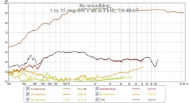
First a baseline, 1 m, 15 deg, BW 6dB at 8 kHz, about 94 dB:
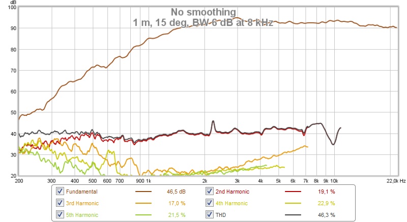
-5 dB point is at 1.3 kHz. (Distortion below ~800 Hz is noise from airplanes, weird peaks between 500 and 2000 Hz are birds.)
With a mild LT (5 dB):
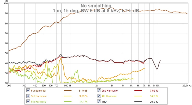
-5 dB point is at 1.0 kHz. Distortion only very slightly raised around 1 kHz.
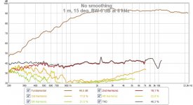
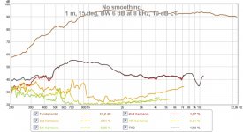
A little more (7.5 dB):

-5 dB point is at 0.9 kHz. Still acceptable as it's 40 dB below for the pass-band.
More (10 dB):

-5 dB point is at 0.83 kHz. The distortion feels a little high.
So XO at 900-1000 Hz is indeed a good option for this tweeter in this horn!
/Anton
The distortion when only applying a HP filter (at 6 kHz) hinted that a lower XO was possible:
There is definitely a downward slope from ~2 kHz which got me thinking that a LT could make my life easier by moving the XO to below 1200 Hz.
First a baseline, 1 m, 15 deg, BW 6dB at 8 kHz, about 94 dB:
-5 dB point is at 1.3 kHz. (Distortion below ~800 Hz is noise from airplanes, weird peaks between 500 and 2000 Hz are birds.)
With a mild LT (5 dB):
-5 dB point is at 1.0 kHz. Distortion only very slightly raised around 1 kHz.
A little more (7.5 dB):
-5 dB point is at 0.9 kHz. Still acceptable as it's 40 dB below for the pass-band.
More (10 dB):
-5 dB point is at 0.83 kHz. The distortion feels a little high.
So XO at 900-1000 Hz is indeed a good option for this tweeter in this horn!
/Anton
Attachments

Last edited:
Mid measurements
I did also experiment with the BP-holes. First I tried removing some material from the volume filler to straighten out the response and remove the odd peaks in the distortion. It had little effect:
View attachment 545540
View attachment 545541
The peaks around 500 Hz are a little lower and only 1.
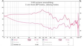
Then I drilled a 14 mm hole closer to the mouth of the horn to make the hole oblong and reduce distance differences for the 8FE200 (which I think is causing the 500 Hz peak):
View attachment 545542
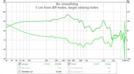
That's a surprisingly small difference, lower peak but same shape. Let's add another hole:
View attachment 545543
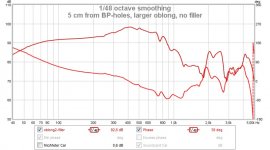
No difference again... Alright let's remove the volume filler, that should make things a lot worse:
View attachment 545545
Oh, it didn't. Actually a little better. How about at 1 m:
View attachment 545545
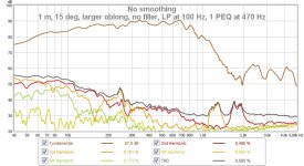
Interesting, let's add a first order LP at 100 Hz to counteract the open baffle slope (and 1 PEQ at 500 Hz to smoothen response):
View attachment 545546
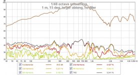
Not bad for ~900 Hz XO. A little high distortion below 200 Hz, but there is no HP filter added. 89 dB for one should be 95 dB if both woofers were installed. Time to make a box and install the other woofer I suppose.
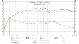
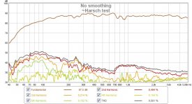
I got a little excited and tried combining the responses (R2604 with 7.5 dB LT and 8 kHz HP, 8FE200 with the above settings) and only trim delay on tweeter:
View attachment 545549
View attachment 545550
Not perfect, but It's only at one point and with one woofer.
/Anton
I did also experiment with the BP-holes. First I tried removing some material from the volume filler to straighten out the response and remove the odd peaks in the distortion. It had little effect:
View attachment 545540
View attachment 545541
The peaks around 500 Hz are a little lower and only 1.
Then I drilled a 14 mm hole closer to the mouth of the horn to make the hole oblong and reduce distance differences for the 8FE200 (which I think is causing the 500 Hz peak):
View attachment 545542
That's a surprisingly small difference, lower peak but same shape. Let's add another hole:
View attachment 545543
No difference again... Alright let's remove the volume filler, that should make things a lot worse:
View attachment 545545
Oh, it didn't. Actually a little better. How about at 1 m:
View attachment 545545
Interesting, let's add a first order LP at 100 Hz to counteract the open baffle slope (and 1 PEQ at 500 Hz to smoothen response):
View attachment 545546
Not bad for ~900 Hz XO. A little high distortion below 200 Hz, but there is no HP filter added. 89 dB for one should be 95 dB if both woofers were installed. Time to make a box and install the other woofer I suppose.
I got a little excited and tried combining the responses (R2604 with 7.5 dB LT and 8 kHz HP, 8FE200 with the above settings) and only trim delay on tweeter:
View attachment 545549
View attachment 545550
Not perfect, but It's only at one point and with one woofer.
/Anton
Last edited:
Broken links?
The links in my last post seem broken. Here are the pics again.
/Anton
The links in my last post seem broken. Here are the pics again.
/Anton
Attachments
-
 Harsch response.jpg81.6 KB · Views: 107
 -
 8FE200 LP+PEQ, larger oblong holes, 1 m, no filler.jpg102.9 KB · Views: 105
 -
 8FE200 RAW, larger oblong holes, 1 m, no filler.jpg104.2 KB · Views: 100
 -
 8FE200 RAW, larger oblong holes, NF, no filler.jpg79.3 KB · Views: 107
 -
 8FE200 RAW, larger oblong holes, NF.jpg74.6 KB · Views: 96
 -
 8FE200 RAW, oblong holes, NF.jpg72.8 KB · Views: 97
 -
 8FE200 RAW, round holes, NF.jpg79.6 KB · Views: 106
 -
 8FE200 RAW, round holes.jpg94 KB · Views: 110
 -
 Harsch dist.jpg97.8 KB · Views: 717
- Home
- Loudspeakers
- Multi-Way
- Synergy attempt without compression driver