Read Walt's post carefully. The // film with the series R isn't really needed. Why don't you just try it with that removed?
Jan
Jan
LTSpice shows if I add some 0.1uF + 1R it dampens some peaks of the LCR of the electrolytic capacitor in the MHz region.
I will definitely take them out today and see what I get. I guess the output cap I use and the 22uF caps at the load may still have too low ESR so I intend to find and buy some high ESR caps. It is Saturday morning now in Sydney and only R.S. Components is open until noon. I will try my luck.
I will definitely take them out today and see what I get. I guess the output cap I use and the 22uF caps at the load may still have too low ESR so I intend to find and buy some high ESR caps. It is Saturday morning now in Sydney and only R.S. Components is open until noon. I will try my luck.
LTSpice shows if I add some 0.1uF + 1R it dampens some peaks of the LCR of the electrolytic capacitor in the MHz region.
I will definitely take them out today and see what I get. I guess the output cap I use and the 22uF caps at the load may still have too low ESR so I intend to find and buy some high ESR caps. It is Saturday morning now in Sydney and only R.S. Components is open until noon. I will try my luck.
So, you can try the simple approach, as recommended, without going anywhere. In my mind, it doesn't make any sense whatsoever to actually seek a special high ESR electrolytic. The circuit is stable with Oscons (ultra low ESR) to cheap lytics (high ESR). Lytic values and ESR aren't critical.
But, it appears what you are missing is the differentiation twixt lytics and film/ceramics. There are good reasons why these high-Q types aren't allowed.
I'd suggest that you heed Jan Didden's advice over what LTSpice whispers in your ear. This circuit/topology was developed before LTSpice even existed. That's not to say that LTSpice isn't a great tool (it is), but years of bench experience do count for something, after all.
wj
PS: you know, it would be helpful to those trying help you out to see your actual schematic. You mention the RC net used for remote sensing, but it isn't shown anywhere.
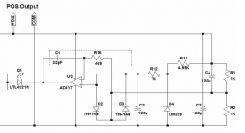
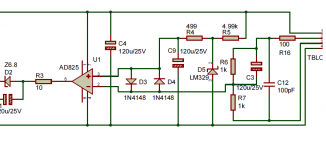
Here is the schematic Jidden posted and a PCB available in the diyAudio store.
I followed this schematic but do not have the 100pF 100R on board. I later tried to have them at the load without success.
The load has 6 single opamps per channel, so totally up 12 opamps.
I will go and remove the 0.1uF + R, the 100p 100R and remove remote sensing now and will see how it goes.
I followed this schematic but do not have the 100pF 100R on board. I later tried to have them at the load without success.
The load has 6 single opamps per channel, so totally up 12 opamps.
I will go and remove the 0.1uF + R, the 100p 100R and remove remote sensing now and will see how it goes.
Attachments

Last edited:
I have just measured my spared, plain, empty PCB of the load and found that the negative rail to ground has nearly 2nF capacitance. The positive rail to ground has 350pF capacitance. The capacitance come from the power and ground planes.
O.K. I took out the 0.1uF + R on the rails. Also took out 1 pair of electrolytic capacitor. Leaving 47uF at the output of the JSR, and 2 x 22uF at the load. These 3 capacitors are classified as low impedance capacitors. I also wired the sensing wires within the JSR board, i.e. no remote sensing now.
It seems the oscillations have reduced. There may still be mild oscillations but they can also be measurement artefacts, I am not sure.
My scope has a limit of 2mV per grid when I use probe setting at X1 but it imposes a 20MHz limit on bandwidth. This is the setting I used.
If I chose probe setting at X10 then it would be 10mV per grid and 150MHz bandwidth. This is the setting I didn't use.
I will post the scope pictures below.
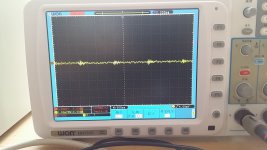
The first picture shows some mild resonances with peak to peak waves no more than 1mV.
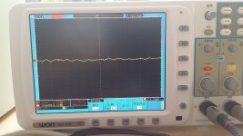
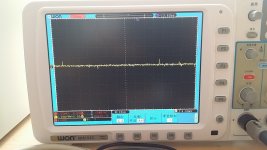
The second picture is the zone-in of the first picture. Note M:20ns so the resonance seems to be around 60MHz.
But then if my scope was limited to 20MHz I am not sure if these make sense or not.
Although my scope was theoretically capable of 150MHz and the probe it comes with could measure that high frequency, I have not used the little coil supplied with it but only the ordinary probe and earth lead. So I am not sure if its RF reading is still reliable or not.
Attachments
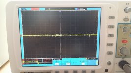
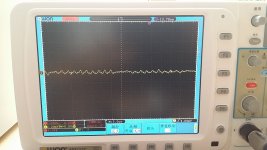
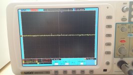
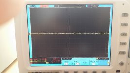
When I set it to 50ns, I see some low level noise. Most of the time it looks like the first photo. Sometimes, I can fetch something like the second photo.
Should I discard these because the scope was limited to 20MHz? or Are they resonances I must get rid of?
Should I discard these because the scope was limited to 20MHz? or Are they resonances I must get rid of?
Attachments

Last edited:
I think with the last scope pics you are into the territory where it is extremely difficult to know what you are measuring, and from where. I think you are home free.
Jan
Jan
It definitely works with resistive load and there is no resonance. But it can resonate with inappropriate load, such as a load with high Q capacitors.
Does the resonance happen in the error amplifier or the pass transistor?
If it happens in the error amplifier, then I guess the latest circuit from Jung's shunt regulator may reduce the chance of resonance.
Can it be a direct replacement?
Does the resonance happen in the error amplifier or the pass transistor?
If it happens in the error amplifier, then I guess the latest circuit from Jung's shunt regulator may reduce the chance of resonance.
Can it be a direct replacement?
Attachments
It definitely works with resistive load and there is no resonance. But it can resonate with inappropriate load, such as a load with high Q capacitors.
Does the resonance happen in the error amplifier or the pass transistor?
If it happens in the error amplifier, then I guess the latest circuit from Jung's shunt regulator may reduce the chance of resonance.
Can it be a direct replacement?
The resonance is 'in the loop' not in a specific part. It is the loop transfer function which is determined by the whole circuit that determines stability.
But why do you want to bend over backwards to battle hi-Q caps. Why do you want to use hi-Q caps? It doesn't make sense.
Jan
There are now no ceramic or film caps at the load. There are low impedance electrolytic caps, only because I have a plenty of them.
I think next I will replace them with generic electrolytic caps. I have to wait until next week when shops are open.
I think next I will replace them with generic electrolytic caps. I have to wait until next week when shops are open.
Perhaps the protection diodes, which I didn't install, help with stability.
Mr. Jung mentioned that the AD825 does not require the protection diode. For that reason I did not install them.
I think of it this way. The diodes have capacitance. So they effectively short the + and - inputs at very high frequencies, with similar effects like the compensation cap across - input and output.
How to do remote sensing correctly, etc.
Remote sensing: This article covers the use of remote sensing, in Fig. 5. It uses an 10 ohm / 0.01uF RC combination, with the R going off the regulator card proper to the remote sense point at the load, and the 0.01uF cap connected between the top of the sense network / 10 ohm R and the Vout terminal of the regulator. This scheme effectively removes the loading wiring etc. from the feedback path at high frequencies, and this improves overall stability. Note that this scheme is at odds with the schematic as shown in post #832. I do not think the setup in #832 is correct, and I wouldn't recommend use of it.
Disclaimer: I wish the readers to note that I have no business interest in this thread, nor any other on DIYAudio. I am simply responding to what first appeared to be an application problem with a circuit that was/is in part attributed to me, Walt Jung. My comments are being offered in a spirit of being helpful to the overall understanding of a popular circuit.
Wrapping up: I agree with Jan's general assessment that HiFiNut's regulator is now likely operating up to snuff, sans the high-Q caps. There does not appear to be any dominant repetitious frequency at Vout, as would be present with a continuous regulator oscillation. But then, one can hardly troubleshoot multiple scope traces from the other side of the world, from an unsure context, at a Gatling gun rep rate. 🙂
Walt Jung
Last edited:
Correct reference to ‘A Universal Shunt Regulator for Audio Applications’
To HiFiNutNut: Please take down your posted snippet from the 'Universal Shunt Reg 122714', as has been copied from my web site within post #832. It is not useful to post a partial schematic excerpt, with or without obtaining prior permission. You do not have such permission, and the article is clearly marked as restricted. Thank you.
For those curious, the complete article in question is listed as the last 2015 Regs and Refs entry, which can be read here.
wj
Thanks. I will replace the low impedance caps and try out the 10R / 0.01uF RC next week.
To HiFiNutNut: Please take down your posted snippet from the 'Universal Shunt Reg 122714', as has been copied from my web site within post #832. It is not useful to post a partial schematic excerpt, with or without obtaining prior permission. You do not have such permission, and the article is clearly marked as restricted. Thank you.
For those curious, the complete article in question is listed as the last 2015 Regs and Refs entry, which can be read here.
wj
Mr. Jung,
Sorry for posting part of your schematic. You have made your article public information and your name and the article were mentioned in my post so there was no infringement of copy right. I thought I showed part of the schematic to reflect that and to force people to read the whole article in your site. Anyway, I am sorry about that.
Dear Moderator,
Please remove the pictures or delete my entire posts for post #814, post #816 and post #832. Many thanks in advance.
Regards,
Bill
Mr. Jung,
Sorry for posting part of your schematic. You have made your article public information and your name and the article were mentioned in my post so there was no infringement of copy right. I thought I showed part of the schematic to reflect that and to force people to read the whole article in your site. Anyway, I am sorry about that.
Dear Moderator,
Please remove the pictures or delete my entire posts for post #814, post #816 and post #832. Many thanks in advance.
Regards,
Bill
The way to properly handle what you did was to provide a direct clickable link to the article, just as I did. That way, no one can be offended, and full/proper credit is given. It is a puzzle to me how you can claim non-infringement of CR, when obviously you copied part of an article that was marked as reserved. 😕
And you certainly did not "force" anyone to read the article, since it wasn't linked.
- Home
- The diyAudio Store
- Super Regulator